FPS PowerSewer V4PS Скачать руководство пользователя страница 8

8

3. INSTALLING COLLECTION TANK

Strict adherence to these proven methods and procedures will ensure 
the long-term performance of your PowerSewer® system. Studies 
by regulatory agencies and trade organizations indicate that the 
most significant source of leaks and failures in underground storage 
structures is improper handling and installation.

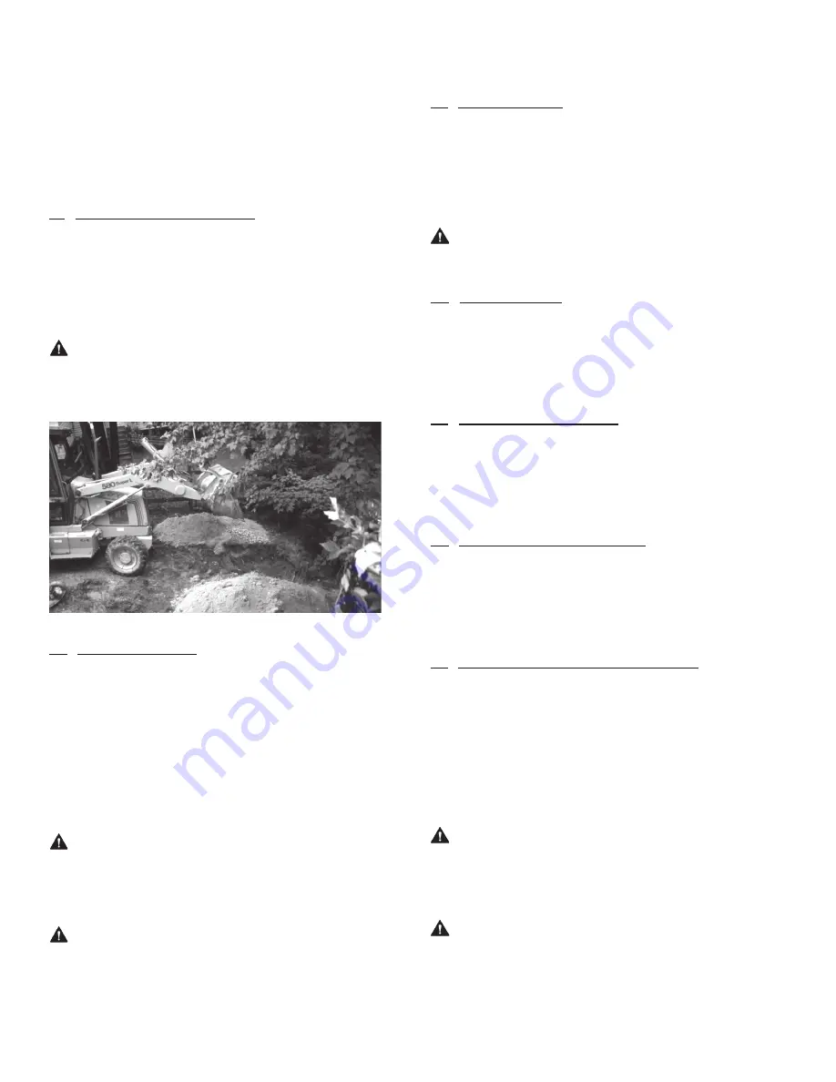
3.1 Excavating for Collection Tank

The excavation should provide adequate space for the collection 
tank, piping, other buried equipment, and for the placement and 
compaction of backfill materials. The size, shape, and wall slope should 
be determined by the site’s soil conditions, depth of excavation, 
shoring and sheeting requirements, and safety regulations.

WARNING


Safe excavation procedures are the 

responsibility of the installer Work safety requirements are defined 
by US Department of Labor 29 CFR part 1926, subpart P, Excavations

3.2 Excavation Location

Excavation for the PowerSewer® collection tank should be made with 
due care to avoid undermining foundations of existing structures 
and contact with overhead or underground utilities. In the absence 
of specific code requirements, maintain a distance of 7' with a slope 
of 45° from the collection tank to adjacent structures, foundations, 
footings, and property lines. Additional distances may be required 
to assure that any loading carried or created by adjacent structures 
cannot not be transferred to the PowerSewer® collection tank.

WARNING


Locate all underground and overhead 

utilities before excavation Call 888-258-0808 at least two business 
days before excavating for a referral to your local “One-Call” utilities 
location center

NOTICE


Do not locate the PowerSewer® excavation in 

drainage areas or other low points on the building lot Failure to 
locate PowerSewer® in proper location will void warranty

3.3 Excavation Depth

Excavate the hole to a depth equal to 4-1/2" plus the collection tank 
depth. When finished, the collection tank rim should be at least 
1-1/2" above final grade. The final grade should slope away from the 
collection tank to avoid surface water from ponding on or around the 
collection tank and cover.

NOTICE


Do not install collection tank rim below  

final grade Below grade installations void the warranty

3.4 Bedding Material

Place and compact gravel bedding to a minimum depth of 6".  
The gravel should be a naturally rounded aggregate, clean and  
free-flowing, with a particle size not less than 1/8" or more  
than 3/4" in diameter.

3.5 Setting the Collection Tank

Ensure that all packaging materials have been removed from the 
PowerSewer® prior to setting the collection tank. Lift and lower the 
collection tank using the methods previously outlined in section 1.4, 
Transportation and Handling.

3.6 Positioning the Collection Tank

Center and level the collection tank on the compacted gravel bedding. 
Fill the collection tank with water to the bottom of the discharge 
piping to limit the movement of the collection tank during backfilling 
and pouring of the concrete ballast.

3.7 Ballasting Collection Tank with Concrete

A concrete ballast anchor must be poured over the collection tank’s 
integral anti-flotation flange to properly secure the collection tank in 
the ground. This will prevent the collection tank from floating up out 
of the ground due to hydrostatic pressure from high water tables. The 
concrete ballast must be a minimum of 8" thick, extending at least 4" 
above the integral anti-flotation flange and 12" out from the collection 
tank. See the installation drawing on page 28 for details.

CAUTION


Concrete ballast is not optional  

Failure to properly ballast the collection tank may result in  
collection tank floating up out of the ground, causing damage 
 to the piping and equipment

NOTICE


This ballast method requires that proper 

compacted backfill material be used as described in section 10, 
Backfilling Around the Collection Tank This is the only acceptable 
method of ballasting the collection tank To receive detailed  
anti-flotation calculations or approval of alternative methods, 
contact Franklin Electric Technical Services at 866-271-2859

Содержание PowerSewer V4PS

Страница 1: ...V4PS Installation Operation Maintenance Manual...

Страница 2: ...and maintenance instructions may result in electrical shock or fire hazard personal injury or death unsatisfactory performance equipment failure and will void the warranty If you have any questions ca...

Страница 3: ...ng the Vent 11 7 1 Vent Coupling Location 7 2 Vent Cap Location 7 3 Vent Pipe Slope 7 4 Solvent Cementing Vent Piping and Fittings 7 5 Installing the Remote Vent Cap 8 Locating and Mounting the Contro...

Страница 4: ...for Field Installation Fiberglass Basin Cover Wet well access cover with polyethylene seal using 3 8 16 SST bolts to fasten cover to basin Spring Release Float Tree Assembly SST Isolated Pump Support...

Страница 5: ...or removal of the manhole bolts and cutting ring bolts 1 Phillips screwdriver to open the control panel cover Small flathead screwdriver used to connect wire to control panel Wire strippers Small chan...

Страница 6: ...tallation should be suspended until the extent of the damage can be determined by an authorized Franklin Electric representative Any field repairs or alterations must be authorized in writing by Frank...

Страница 7: ...aggregate for collection tank foundation Concrete for collection tank ballast minimum 7 cubic feet Approved backfill materials see section 10 1 Approved Backfill Materials Determine main electrical su...

Страница 8: ...im should be at least 1 1 2 above final grade The final grade should slope away from the collection tank to avoid surface water from ponding on or around the collection tank and cover NOTICEDo not ins...

Страница 9: ...ary 4 4 Applying Solvent Cement Solvent cement must be applied immediately to the primed surfaces before the primer dries in an alternating three coat application Using a brush or applicator sized no...

Страница 10: ...e Then dry fit service lateral from property into elbow or sanitary tee Make any necessary adjustments to the drop inlet pipe for a proper fit NOTICEIf a cleanout is not available in the property serv...

Страница 11: ...utlined in section 4 0 Solvent Cementing Joints NOTICEJoints and fittings in the vent piping must be watertight If not ground and surface water could infiltrate the PowerSewer system resulting in unne...

Страница 12: ...ause fire or damage to the pump control panel or cause severe personal injury and will immediately void the warranty Control Panel for Pump Power Wiring Preparation Strip back the outer jacket of the...

Страница 13: ...as defined by ASTM D 2321 include clean gravels and sands with less than 5 fines and clean compactible soil that contain less than 12 fines Class 2 materials consist of rounded materials and are less...

Страница 14: ...e junction box The length of the power cord is 10 long regardless of the size of the tank Do not leave extra cord inside of wet well The cable may become entangled in the rotating cutters or interfere...

Страница 15: ...tor features with the property owner 12 OPERATION The PowerSewer grinder pump sewer system is equipped with a float control system that continuously controls the grinder pump operation 12 1 Automatic...

Страница 16: ...List Equip yourself with the proper installation operation and maintenance tools before performing any work on or near the PowerSewer system Review section 1 2 Installation and Maintenance Tool List...

Страница 17: ...draulic Diaphragm Seal TPV Pump Stand Off PVC 1 1 4 Discharge Pipe SST 2 HP Centrifugal Grinder Pump IGP M IGP A IGPH M IGPH A IGPDS M IGPDS A Discharge Depth See Table A Basin Height See Table H 42 1...

Страница 18: ...ll Bearing Upper Single row ball 6203 Ball Bearing Lower Single row ball 6306 Seal Housing Cast iron with epoxy coating Mechanical Seal Carbon Ceramic Volute Cast iron with epoxy coating Impeller Bras...

Страница 19: ...and third party approval Motor Cover Cast iron with epoxy coating Motor Cover O ring Nitrile Motor Design Single phase capacitor start capacitor run or three phase depending on pump model Insulation C...

Страница 20: ...hes must be rated a minimum of 2 Amps at 120 V 208 230 VAC PUMP POWER CABLE 208 230 VAC 115 VAC 1 PHASE 60 HERTZ POWER SUPPLY CONTROL PANEL 515351 515357 COMMON RUN START PANEL GRD BLUE BLACK ORANGE B...

Страница 21: ...60 C copper wire minimum 6 Level switches must be rated a minimum of 2 Amps at 120 V THREEPHASE IGP IGPHMANUALGRINDER Wiring Diagram 208 240 480 600 VAC 3 PHASE 60 HERTZ POWER SUPPLY INCOMING POWER CO...

Страница 22: ...Ball Bearing Upper Single row ball 6203 Ball Bearing Lower Single row ball 6306 Seal Housing Cast iron with epoxy coating Mechanical Seal Carbon Ceramic Volute Cast iron with epoxy coating Impeller Br...

Страница 23: ...Motor Design Single phase capacitor start capacitor run Insulation Class F Overload Protection Internal on winding thermal protector Motor Shaft AISI 300 series stainless steel Ball Bearing Upper Sin...

Страница 24: ...M FLOAT BLACK BLACK BLACK WHITE WHITE WHITE GREEN WHITE BLACK TANK JUNCTION BOX MOUNTED IN TANK DRY WELL NOTE This is a control drawing only and does not re ect the actual locations of cable penetrati...

Страница 25: ...with fluoroelastomer FKM bellows and stationary ceramic with fluoroelastomer FKM O ring Lower Type 21 spring loaded rotating silicon carbide with fluoroelastomer FKM bellows and stationary silicon car...

Страница 26: ...RUN START SEAL FAIL PUMP OFF FLOAT PUMP ON FLOAT HIGH LEVEL ALARM FLOAT TANK JUNCTION BOX MOUNTED IN TANK DRY WELL SENSOR CABLE NOTE This is a control drawing only and does not re ect the actual locat...

Страница 27: ...TANK JUNCTION BOX MOUNTED IN TANK DRY WELL 12 AWG PUMP CABLE 125 FT MAX COMMON RUN START TB4 SEAL FAIL 18 AWG FLOAT CABLE 18 AWG SEAL FAIL CABLE NOTE This is a control drawing only and does not re ect...

Страница 28: ...t check valve not provided shown for reference only 10 Stop valve not provided shown for reference 11 Force main or gravity line 12 Pump power and or control float control direct bury cable or continu...

Страница 29: ...ty does not cover any labor or shipping charges The Company shall not be liable for any costs or charges attributable to any product testing maintenance installation repair or removal or for any tools...

Страница 30: ...RN AND OR INSTRUCT LOSS OF OTHER PRODUCTS OR COSTS OF ENVIRONMENTAL REMEDIATION OR DIMINUTION IN PROPERTY VALUE THE REMEDIES OF THE PURCHASER SET FORTH HEREIN ARE EXCLUSIVE AND THE LIABILITY OF THE CO...

Страница 31: ...31 NOTES...

Страница 32: ...Road Fort Wayne IN 46809 Tel 866 271 2859 Fax 886 281 2709 www franklinengineered com Form 998076 Rev 002 12 20 For technical assistance please contact 866 271 2859 www franklinengineered com FPSEngin...

Отзывы: