29
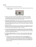
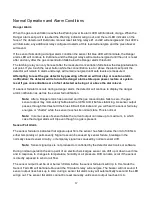
Gas Sensor Replacement
Complete Sensor with 4-20mA Transmitter Board
Tools Required:
•
Slotted or Phillips Screwdriver
•
Needle nose Pliers
1. Disconnect the AC power from the detector.
2. Remove the sensor enclosure from the wall.
3. Remove the front cover of the sensor enclosure.
4. Carefully pull off the orange wire connector.
5. Flip the enclosure so that you can see the bulk head nut. Place the tips of a pair of needle nose
pliers in the two holes of the sensor bulk head nut. Turn the ring counterclockwise to loosen the
ring, and remove the entire sensor from the enclosure.
6. Reverse this procedure to install the new sensor with transmitter board.
7. After a sufficient warm up period check the zero point of the sensor and adjust if needed.
8. Conduct the sensor response test. If the sensor fails this test a full calibration is required.
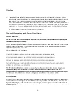
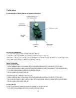
Ready Advanced Ammonia Sensor with 4-20mA Transmitter Board
CAUTION:
This component is susceptible to Electrostatic Discharge (ESD) when being installed
or adjusted.
1.
Disconnect the AC power from the detector.
2.
Remove the sensor enclosure from the wall.
3.
Remove the front cover of the sensor enclosure.
4.
Discharge static electricity from your body and tools by touching a metal part of the
equipment or use a ground strap connected to an earth ground.
5.
Pull off the two power connectors. Note the sensor module offers reverse polarity protection,
so the power supply can be connected in either direction.
6.
Remove the mounting screws.
7.
Reverse this procedure to install the new sensor.
8.
After a sufficient warm up period check the zero point of the sensor and adjust if needed.
9.
Conduct the sensor response test. If the sensor fails this test a full calibration is required.
Содержание FX-Mini
Страница 2: ...2 Page intentionally left blank...
Страница 30: ...30 Gas Sensor Components See page 26 for Ammonia Ozone and Hydrogen Cyanide sensor components...
Страница 35: ...35...

