Foxcroft FX-Mini Скачать руководство пользователя страница 25

25 


Calibration


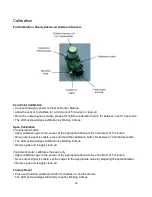
Full Calibration, Toxic Gas Sensors 

The correct voltage output for the target gas being used can be determined as follows: 

(16 x gas concentration) / range of  4 x 10mV 


a.  Example: Calibrating a hydrogen sulfide sensor to a range of 0-50ppm using a 

calibration gas concentration of 20ppm: 

(16 x 20) / 50 + 4 + 10 = 104 mV 

12. With the correct reading displayed on the detector calibration is complete, re-assemble the 

detector. 

Caution: Be sure to remove the calibration nose before placing the detector into service

.


Never operate the sensor with the calibration nose inserted. 

Caution: If the sensor or detector will not allow you to fully adjust the displayed 
concentration to match that of the calibration gas then you must replace the gas sensor.


Full Calibration, Oxygen Sensors 

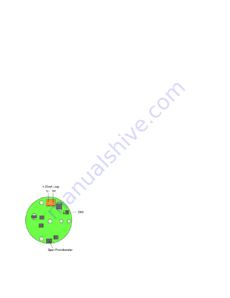
Calibration should be carried out in ambient air, and is done simply by adjusting the span potentiometer 
until a reading of 20.9% on a scale of 0-25% is displayed on the LED display. Zero point calibration is 
not required. Sensor output can be monitored by connecting a multi-meter set to mA to the 4-20mA 
loop connector, or to the millivolt connector CN2 using a meter set to VDC. 


Oxygen sensors alarm as concentrations, and therefore sensor output, decreases. A 4 mA Oxygen 
sensor output corresponds to 16% Oxygen by volume, which is the Danger alarm trip point.  

1.  Connect the meter leads, observing polarity, to millivolt 

test connector CN2 or to the 4-20mA loop connector. Make sure 
your meter is set to the correct scale. 

2.  Ensure that the calibration nose is removed, expose the 

sensor to ambient air and allow sensor output to stabilize. 

3.  Using a small non-metallic screwdriver with a 1.2 x 0.5 

mm tip, adjust the span potentiometer until a reading of 17.4 mA 
is shown (or 174 mV across CN2). These values correspond to 
20.9% O2 on a scale of 0-25%. 

4.  The calibration is now complete. 

5. 

To test the alarm functions see the following section 

“Sensor Response (Bump) Test. This test requires


a mixture of 

16% Oxygen with the balance in Nitrogen and a 0.5 LPM fixed 

flow rate regulator with C10 connection. 


Содержание FX-Mini

Страница 1: ...1 Foxcroft FX Mini FX Mini R Single Channel Toxic Gas Detector Operating Manual Document OMFXMINI102019...

Страница 2: ...2 Page intentionally left blank...

Страница 3: ...tions 13 Startup 14 Normal Operation Alarm Set Points and Conditions 15 Normal Operation and Alarm Conditions Danger Sensor Fail Alarms 16 Normal Operation and Alarm Conditions Sensor Fail Oxygen Sens...

Страница 4: ...d LED indicator light sound the integral audible buzzer at the danger level only and energize the appropriate relays that have been assigned The electrochemical gas sensing cell generates a voltage th...

Страница 5: ...sensor be tested by means of a certified gas standard at least once every six months Warning If the FX Mini is altered in any way the warranty will be voided Example drilling additional holes in the e...

Страница 6: ...6 FX Mini Gas Detector Illustration All in One Option 1 Main Circuit board 2 AC DC Power Supply 3 Gas Sensor 4 10A relay card 5 Silence Reset Button 6 Buzzer...

Страница 7: ...f the potential hazard area The devices are connected by 25 feet of 22 AWG shielded cable up to 2 000 feet of cable is available optionally Wiring connections to the gas sensor are color coded to reco...

Страница 8: ...y connections to the circuit board Before touching the circuit board touch an earth grounded metal surface such as the detector s power supply guard a metal pipe or conduit to discharge any static ele...

Страница 9: ...ole USA plug 4 ft cord Class II power Agency Approvals CE CUL CB FC The power cord plugs into a standard NEMA 5 15R receptacle 24VDC NOTE Detectors for Ammonia Hydrogen Cyanide and Ozone use an AC to...

Страница 10: ...limit current to the relay to less than 10 amps Relay 1 Danger Relay 2 Danger Relay 3 Warning Relay 4 Sensor Fail O Relay red LED O Relay card power on LED Relay test buttons yellow highlight Relays...

Страница 11: ...Unpacking The detector is shipped with a piece of cardboard that covers and protects the gas sensor remove this prior to installation After unpacking it is recommended to save the shipping carton and...

Страница 12: ...ate the sensor with the sensing chamber opening pointing down toward the floor near the gas source where the normal air flow pattern will carry the gas to the sensor Do not install in dusty or dirty a...

Страница 13: ...Sensor Housing Dimensions 13 Dimensions Attach the wall mounting feet to the rear of the main enclosure using 10 diameter re not included near the potential leak source taking into account the locatio...

Страница 14: ...non latching to alarm at the Sensor Fail level Tip Test your wiring by pushing the test buttons on the relay card Tip If you think the warning alarm level may trigger nuisance alarms do not assign a r...

Страница 15: ...rated before shipment differences in air pressure temperature and relative humidity at the installation site may cause the zero point and consequently the alarm trip points to shift slightly 5 The sen...

Страница 16: ...ndicator flashing on the main circuit board and a green power on LED illuminated on the relay card Alarm Set Points and Conditions The FX Mini includes two gas alarm set points and a sensor fail alarm...

Страница 17: ...ay the danger alarm notification as well as the sensor fail notification Note After a Danger alarm has occurred and the gas concentration falls to zero the gas sensor output may momentarily fall below...

Страница 18: ...The responsiveness of electrochemical sensors will vary with environmental conditions Sensor response may be higher or lower depending on actual environmental conditions Gas Exposure The electrochemic...

Страница 19: ...evels the sensor will progressively become more non linear and take increasingly longer to recover as the sensing electrode is unable to consume all the gas diffusing to it If the gas level is increas...

Страница 20: ...response time of the sensor s or a minimum level of response achieved such as 80 of gas concentration applied Note this check is not intended to provide a measure of calibration accuracy Calibration c...

Страница 21: ...rate a chlorine gas sensor with bleach pool chlorinating chemicals or by producing chlorine gas with a mixture of bleach and an acid Any sensor adjustment made with such gases or fumes or without the...

Страница 22: ...osure You may leave the sensor by unscrewing the mounting ring and pulling the sensor out of the Use the orange connector or the gray plastic sensor body to handle the gas sensor Do not handle the sen...

Страница 23: ...ers Span calibration requires a gas standard calibration kit The gain is factory set and should never be adjusted Full Calibration Toxic Gas Sensors 1 Make sure the zero point is set accurately if not...

Страница 24: ...s before rising due to differences in humidity and pressure between the gas in the cylinder and the gas sensor 6 Allow five minutes sometimes slightly less for the readings to stabilize 7 Adjust the s...

Страница 25: ...displayed on the LED display Zero point calibration is not required Sensor output can be monitored by connecting a multi meter set to mA to the 4 20mA loop connector or to the millivolt connector CN2...

Страница 26: ...appropriate flow rate for a minimum of 5 minutes Once output signal is stable press and hold the calibration button for between 12 and 60 seconds The LED acknowledges calibration by blinking 8 times...

Страница 27: ...oint setting 2 Install the calibration nose into the sensor opening collar be sure the nose is seated and the sealing caps are removed 3 Connect the target calibration gas sample tubing to the nose Ox...

Страница 28: ...he board off of the sensor 7 Remove and discard the 3 mounting screws They are metric The new sensor will come with 3 new 2 56 screws that match the thread inserts in the new sensor Keep the collar me...

Страница 29: ...sensor response test If the sensor fails this test a full calibration is required Ready Advanced Ammonia Sensor with 4 20mA Transmitter Board CAUTION This component is susceptible to Electrostatic Di...

Страница 30: ...30 Gas Sensor Components See page 26 for Ammonia Ozone and Hydrogen Cyanide sensor components...

Страница 31: ...Reset Button 1 Dual function NC pushbutton first push silences the buzzer the second resets alarms relays Operating Voltage Regulated 12VDC Power Supply by included AC DC power supply below or by 12VD...

Страница 32: ...to protect the detector in outdoor installations Outdoor installations require non standard UV stabilized enclosures Battery Backup A separate 300VA external battery backup UPS is available part FX BB...

Страница 33: ...must be freight prepaid and include the following information 1 A clearly written description of the malfunction 2 Name of person to contact and the phone number where they can be reached 3 Proper ret...

Страница 34: ...uthorized repair Buyer agrees to hold Foxcroft Equipment Service harmless from all claims for damages arising out of injury or death to any person or damage to any facility or any other property or lo...

Страница 35: ...35...

Страница 36: ...quipment Service Co Inc 2101 Creek Road P O Box 39 Glenmoore PA 19343 Tel 800 874 0590 610 942 2888 Fax 610 942 2769 Email sales foxcroft com Web www foxcroft com Serial Number Label for FX Mini Toxic...

Отзывы: