2-1. Unpacking and inspection
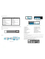
Remove the UPS from its package and make sure that all the following items are included:
Carefully inspect the UPS to check for any damages that may have occurred during shipping. Should any evidence of damage be
found or if some parts are missing, do not turn the UPS on; you must immediately notify the carrier or dealer where you purchased
the unit.
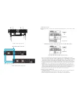
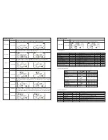
2-2. UPS front and rear panel views
Front view
Rear panel
2-3. UPS installation
Installation and wiring must be performed by qualified personnel, and in accordance with the local electrical regulations and codes.
Also, you must observe the following instructions:
1) Make sure the mains wire and breakers in the building are enough for the rated capacity of UPS to avoid the hazards of
electric shock or fire.
Note:
Do not use a wall receptacle as the input power source for the UPS, as its rated current is less than the UPS maximum
input current. Failure to do so may result in a broken or burned out receptacle.
2) For safety considerations, turn off the mains switch in the building before installation.
3) Turn off all the devices before connecting them to the UPS.
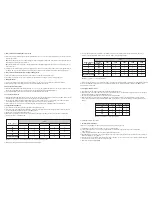
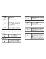
4) Wiring sizes should be installed in accordance with the following table:
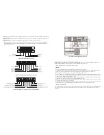
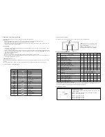
16. Isolation transformer output terminals
17. Isolation transformer input terminals
18. Isolation transformer input grounding
19. Isolation transformer output grounding
20. Battery pack ground
21. UPS secondary ground for battery pack
22. Output breaker
23. Maintenance bypass switch
24. Output control signal slot
25. Maintenance bypass ground
26. Maintenance bypass output terminals
27. Maintenance bypass UPS output terminals
28. Maintenance bypass UPS input terminals
29. Utility input terminals
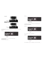
1. Parallel current port
2. Parallel data ports
3. External battery connector
4. Intelligent slot
5. RS-232 communication port
6. USB communication port
7. Emergency power off (EPO) connector
8. Input circuit breaker
9. Output terminals
10. Ground
11. Input terminals
12. Cooling fans
13. External maintenance bypass switch
14. Battery pack output circuit breaker
15. External battery connector
Isolation transformer version (110V)
Standard version (220V)
- Online UPS
- Battery bank
- Isolation transformer
- CD with ForzaTracker monitoring software
- USB cable
- One parallel cable
- Share current cable
- Battery pack cable
- Isolation transformer cable
- Rack mounting brackets and hardware
- Tower support base
- User manual
- Warranty certificate
- Online UPS
- Battery bank
- CD with ForzaTracker monitoring software
- USB cable
- One parallel cable
- Share current cable
- Battery pack cable
- Rack mounting brackets and hardware
- Tower support base
- User manual
- Warranty certificate
Wiring specification (AWG)
Model
Input
Ground
Output
Battery
6K
10K
10
8
10
8
10
8
Diagram 1: UPS unit
Diagram 2: Battery pack
Diagram 3: Isolation transformer
input and output terminals
Diagram 4: Maintenance bypass switch with breaker input and output terminals
19
16
17
18
15
20
14
BYPASS
LINE
BATT
FAULT
OFF/ESC
TEST/UP
MUTE/DOWN
ON/ENTER
5
6
7
13
4
3
1
2
12
9
10
11
8
21
29
25
26
28
27
25
22
23
24
Содержание FDC-106KMR-ISO
Страница 17: ......


