


• It is not recommend the use of this UPS in life support applications where failure or malfunctions of the product can be reasonably
expected to cause failure of the life support device or to significantly affect its safety or effectiveness. Do not use this equipment
in the presence of a flammable anesthetic mixture with air, oxygen or nitrous oxide.
• Connect your UPS power module’s grounding terminal to a grounding electrode conductor.
• The UPS is connected to a DC energy source (battery). The output terminals may be live when the UPS is not connected to an AC
supply.
• This is a product for commercial and industrial application in the second environment – installation restrictions or additional
measures may be needed to prevent disturbances.
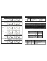
• In accordance with safety standard EN-IEC 62040-1, installation has to be provided with a “Backfeed protection” system, as a
contactor for example, which will prevent the appearance of voltage or dangerous energy in the input mains during a mains fault.
There is no standard backfeed protection inside of the UPS. Please isolate the UPS before operating the product according to
Diagram 1. The isolation device must be able to carry the UPS input current.
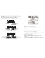
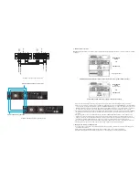
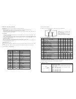
Diagram 1: External backfeed protection wiring
Warning labels should be placed on all primary power switches installed in places away from the device to alert the electrical
maintenance personnel of the presence of a UPS in the circuit. The label will bear the following or an equivalent text:
Do not disconnect the earth conductor cable on the UPS or the building wiring terminals at any time since this would cancel the
protective earth of the UPS system and of all connected loads.
The UPS system features its own, internal current source (batteries). The UPS output sockets or output terminals block may be
electrically live even if the UPS system is not connected to the building wiring outlet.
In order to fully disconnect the UPS system, first press the
OFF
button and then disconnect the power from the AC mains.
Do not allow any kind of liquid or foreign object to enter this UPS unit. Do not place beverages or any other containers with liquid
on or nearby the unit.
The UPS can be operated by any individual with no previous experience.
1-5. Standards
2. Installation and operation
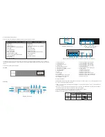
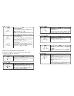
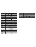
The Forza Atlas series is offered in four different models, as shown in the table below.
* Safety
Safety conformance: IEC/EN 62040-1,UL1778 (5th Edition)
* EMI
Conducted emission..............................:IEC/EN 62040-2,FCC PART15 CLASS A
Radiated emission.................................:IEC/EN 62040-2,FCC PART15 CLASS A
* EMS
ESD.........................................................:IEC/EN 61000-4-2
RS...........................................................:IEC/EN 61000-4-3
EFT..........................................................:IEC/EN 61000-4-4
SURGE....................................................:IEC/EN 61000-4-5
CS............................................................:IEC/EN 61000-4-6
Power-frequency magnetic field...............:IEC/EN 61000-4-8
Low frequency signals..............................:IEC/EN 61000-2-2
Level 4
Level 3
Level 4
Level 4
Level 3
Level 4
Model
Capacity
FDC-106KMR with isolation transformer
FDC-110KMR with isolation transformer
FDC-206KMR
FDC-210KMR
6000VA /6000W
10000VA/ 1000W
6000VA /6000W
10000VA/ 10000W
Q
T
L/L1
N/L2
L/L1
External Distribution Panel
UPS
N/L2
B
Coil Remote Switch
Q
Magneto_Thermal Input Main Switch
T
AC Contactor as backfeed protection device
N/L2
Neutral L/L2
L/L1
L1 Line Input
Legend
There can be no derivation in the line that goes from the «Backfeed protection» to the UPS, as the
standard safety would be infringed.
Before working on this circuit
- Isolate Uninterruptible Power System (UPS)
- Then check for Hazardous Voltage between all terminals
including the protective earth
Risk of Voltage Backfeed
Содержание FDC-106KMR-ISO
Страница 17: ......