• When replacing the battery, make sure to use the same type and number of sealed lead-acid batteries specified.
• Do not dispose of batteries in a fire. Batteries may explode if exposed to high temperatures.
• Never try to open a battery. The cell contains a toxic electrolyte which is harmful to the skin and eyes.
• Replace the fuse only with the same type and amperage in order to avoid fire hazards.
• Do not dismantle the UPS system.
2. Operation
2-1. Unpacking and inspection
Remove the UPS from its package and make sure that all the following items are included:
• One UPS unit
• One user manual
• One monitoring software CD (ForzaTracker)
• One USB cable
• IEC C13 to Argentina Type I cable
• Warranty certificate
Carefully inspect the UPS to check for any damages that may have occurred during shipping.
Should any evidence of damage be found or if some parts are missing, do not turn the UPS on; you must immediately notify the carrier
or dealer where you purchased the unit.
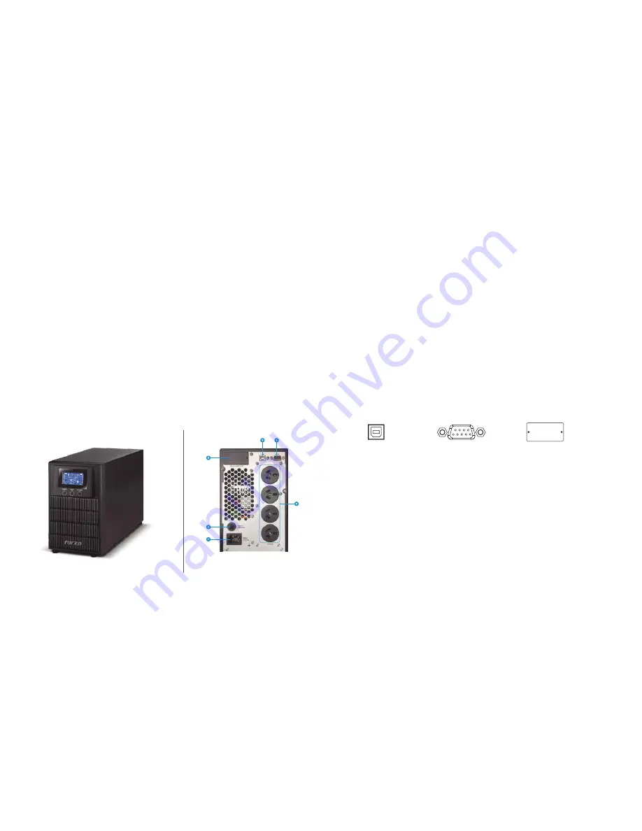
2-2. UPS diagram
Front
panel
view
Rear
panel
view
FDC-1002T-A/FDC- 2002T-A
1. AC input
2. Input circuit breaker
3. USB communication port
4. RS-232 communication port
5. SNMP intelligent slot (optional)
6. Output receptacles
2.3. Installation procedure
Choose location
Install the UPS unit in any protected environment that provides adequate airflow around the unit, and free from excessive dust, corrosive
fumes and conductive contaminants. Do not operate your UPS in an environment where the ambient temperature or humidity is high.
For best performance, keep the indoor temperature between 0° C and 40° C. Place the UPS unit at least 20 cm away from monitors to
avoid interference.
2-4. UPS connections
2-4.1 UPS input connection
Plug the UPS into a two-pole, three-wire, grounded receptacle only. Avoid using extension cords or adapter plugs.
2-4.2 UPS output connection
• For socket-type outputs, simply connect devices to the outlets.
Communication port:
To allow for unattended UPS shutdown/start-up and status monitoring, connect one end of the communication cable to the
USB/RS-232 port, and the other end to the communication port of your PC. With the monitoring software installed, you can schedule
UPS shutdown/start-up and monitor its status through a PC.
The UPS is equipped with intelligent slot perfect for either SNMP card. When installing a SNMP card in the UPS, it will provide advanced
communication and monitoring options.
Note:
The USB and RS-232 ports cannot be used at the same time.
Turning on the UPS
Press the
ON/Mute
button on the front panel for two seconds to power on the UPS.
Note:
The battery charges fully during the first five hours of normal operation. Do not expect full battery run capability during this initial
charge period.
2-5. ForzaTracker monitoring software
ForzaTracker is a new generation of UPS monitoring software, which provides user-friendly interface to monitor and control your UPS
system. This unique software provides safe auto-shutdown for multi-computer systems during power failures. With this software, users
can monitor and control any UPS on the same LAN no matter how far they might be from the UPS.
Intelligent slot
RS-232 port
USB port


