


ForeRunner
ATM Switch Network Configuration Manual
C - 23
Con
v
er
ti
ng fr
om
F
T
-PNNI
to PNNI
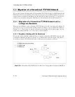
Converting from FT-PNNI to PNNI
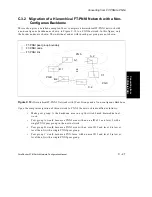
C.3.1.2.1.3
Convert Peer Group A
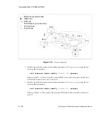
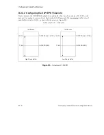
Peer group A is chosen next to be migrated to PNNI. Step 7 from the conversion of peer group
C is unnecessary in peer group A’s case because there is only one border node in this peer
group, and, therefore, the peer group does not get partitioned during the migration. Also,
ensure that the area ID of the PNNI nodes in peer group A is different from the area ID of peer
group C. Make 6 the area ID of peer group A and make the level 5 (the same level as peer
group C).
Migrate all of the nodes in peer group A using the same method that was used to migrate peer
group C in Section C.3.1.2.1.2.
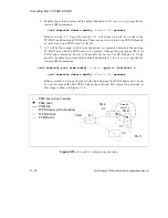
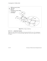
C.3.1.2.1.4
Convert the Backbone
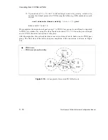
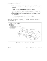
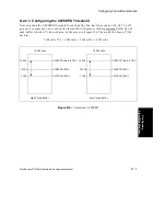
Once all of the nodes in peer group A have been modified, the link between A.1 and C.1 will
become an inoperational PNNI link because it is between two gateway switches and because
the peer group IDs of the PNNI nodes on A.1 and C.1 do not match. However, connectivity
between the peer groups is still possible through the FT-PNNI backbone.
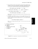
1.
Modify the default protocol of the default domain in C.1 to
pnni
using the follow-
ing AMI command:
conf atmroute domain modify
<domain ID>
pnni
Reboot switch C.1.
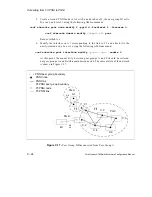
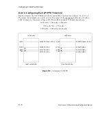
2.
Create a second PNNI node in C.1 with a node index of 2, the peer group ID set to
D, area 3, and level 2 using the following AMI commands:
conf atmroute pnni node modify 2 -pgid d -forelevel 2 -forearea 3
conf atmroute domain modify
<domain ID>
pnni
Reboot switch C.1. This is the first node in the backbone area.
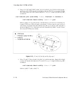
3.
Modify the interface on C.1 corresponding to the link to A.1 and attach it to the
newly-created node 2 on C.1 using the following AMI command:
conf atmroute pnni interface modify
<port>
<vpi>
-nodeix 2
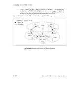
4.
Change the default protocol of the default domain in A.1 to
pnni
using the follow-
ing AMI command:
conf atmroute domain modify
<domain ID>
pnni
Reboot switch A.1. The FT-PNNI link between A.1 and B.1 is lost at this stage and
connectivity between peer group A and the rest of the network is severed.
Содержание forerunner series
Страница 6: ......
Страница 16: ...TOC 10 ForeRunner ATM Switch Network Configuration Manual Table of Contents ...
Страница 20: ...LOF 4 ForeRunner ATM Switch Network Configuration Manual List of Figures ...
Страница 22: ...LOT 2 ForeRunner ATM Switch Network Configuration Manual List of Tables ...
Страница 30: ...viii ForeRunner ATM Switch Network Configuration Manual Preface ...
Страница 144: ...3 58 ForeRunner ATM Switch Network Configuration Manual Configuring an Emulated LAN ...
Страница 180: ...6 12 ForeRunner ATM Switch Network Configuration Manual ATM Forum PNNI ...
Страница 220: ...9 6 ForeRunner ATM Switch Network Configuration Manual Configuring Timing ...
Страница 300: ...D 24 ForeRunner ATM Switch Network Configuration Manual Configuring FramePlus Modules ...
Страница 308: ...Acronyms 8 ForeRunner ATM Switch Network Configuration Manual Acronyms ...
Страница 346: ...Glossary 38 ForeRunner ATM Switch Network Configuration Manual Glossary ...
Страница 352: ...Index 6 ForeRunner ATM Switch Network Configuration Manual Index ...


