

ForeRunner ATM Switch Network Configuration Manual
6 - 9
A
T
M F
o
rum
PNNI
ATM Forum PNNI
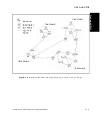
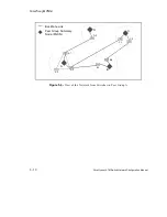
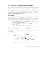
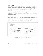
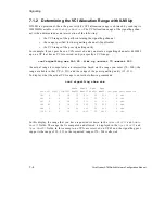
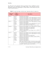
In Figure 6.4, the two nodes configured in switch S1 belong to different areas, and so they do
not share the same link-state topology database. The same is true for the nodes configured in
switch S4. Dynamic reachability leaking takes place among the nodes in switch S1, enabling
end systems in Area A to reach other end systems in Area B, and vice versa within Domain 1.
The same applies to the nodes in switch S4.
The node in switch S2 and the node in switch S3 belong to two different areas, each of which is
part of a different domain. Exchange of reachability information between the nodes will occur
over the IISP link that has been statically configured between the domains.
6.3.2.2.1
Configuring Domains
Domains only need to be configured on split switches and gateway switches; i.e., switches that
belong to multiple areas. Other switches operate properly without domain configuration.
One FT-PNNI domain (with domain index 1) is pre-configured by default on switches running
ForeThought 5.2.x. This domain cannot be deleted, but the information within the domain can
be changed. Multiple domains can be configured on a switch. For each domain, the following
parameters can be changed:
•
The domain name, which is optional, can be configured for easier manageability.
However, the name of the default domain cannot be changed.
•
The domain protocol, which sets the routing protocol for the switch, can be set to
ftpnni
,
pnni
, or
gateway
. This parameter can also be changed on the default
domain. The default setting is
ftpnni
. If you want to configure a split switch,
you must change the domain protocol to
pnni
. If you want to configure a gate-
way switch, you must change the domain protocol to
gateway
.
•
The domain prefix can be changed. This sets the default 13-byte NSAP prefix used
by the switch’s routing protocol(s).
•
The default summarization parameter can also be modified. This tells the switch’s
routing protocol(s) to use the peer group mask (in the case of FT-PNNI) or the
PNNI level (in the case of PNNI) to determine the length of the mask to use on the
prefix to form the peer group ID.
•
A signalling interface (port/VPI) can be associated with a particular domain,
while the routing interface (port/VPI) for that signalling interface can be associ-
ated with a particular routing node within that domain.
For more information about changing these parameters, see Chapter 1 of the AMI
Configuration Commands Reference Manual.
Содержание forerunner series
Страница 6: ......
Страница 16: ...TOC 10 ForeRunner ATM Switch Network Configuration Manual Table of Contents ...
Страница 20: ...LOF 4 ForeRunner ATM Switch Network Configuration Manual List of Figures ...
Страница 22: ...LOT 2 ForeRunner ATM Switch Network Configuration Manual List of Tables ...
Страница 30: ...viii ForeRunner ATM Switch Network Configuration Manual Preface ...
Страница 144: ...3 58 ForeRunner ATM Switch Network Configuration Manual Configuring an Emulated LAN ...
Страница 180: ...6 12 ForeRunner ATM Switch Network Configuration Manual ATM Forum PNNI ...
Страница 220: ...9 6 ForeRunner ATM Switch Network Configuration Manual Configuring Timing ...
Страница 300: ...D 24 ForeRunner ATM Switch Network Configuration Manual Configuring FramePlus Modules ...
Страница 308: ...Acronyms 8 ForeRunner ATM Switch Network Configuration Manual Acronyms ...
Страница 346: ...Glossary 38 ForeRunner ATM Switch Network Configuration Manual Glossary ...
Страница 352: ...Index 6 ForeRunner ATM Switch Network Configuration Manual Index ...


