


27
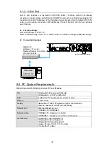
Example 3: To Control Slot 1 Module by Remote Control Connection.
When the Control Base Port setting is 57000, input 172.16.0.10 for the IP address. Input
57001 for the port number.
Similarly, input 57002 for the port number of Slot 2.
IMPORTANT
Multiple port numbers for HTTP Base Port/ SNMP Base Port/ Control Base Port, are used in
order to prevent system glitches from occurring when a PC connects to and control multiple
modules on the USF-105S via the external LAN A port.
The port numbers of USF-105S and other components should all be set to different settings in
the control PC.
LAN 1 Settings
LAN 1 port that connects to the built-in USF-105S switching hub can be set.
Item
Factory Setting
Description
IP Address
192.168.0.10
Sets IP Address of the LAN 1 port.
Subnet Mask
255.255.255.0
Sets Subnet Mask of the LAN 1 port.
Gateway
192.168.0.10
Sets Gateway of the LAN 1 port.
Control Port
50000
Sets the TCP/UDP port number through which Remote
Control Unit accesses to the LAN 1 port.
Subnet Mask and Gateway setting values apply to all modules mounted in slots 1 to 5.
IP Address and Gateway should be the same address when utilizing the router function to
control the Web display and SNMP together through LAN A.
IMPORTANT
LAN 1 and modules in Slot 1 to 5 are connected to the built-in USF-105S switching hub.
Accordingly, avoid using the same IP addresses of LAN 1 port and Slot 1 to 5 as those of devices
in the network. If the addresses are improperly set, network failure may occur and produce
instable operation or web displays may not appear.
Slot Settings
Two procedures allow each slot IP address to be set one by one, or in one operation.
Setting one by one
Input IP addresses in Slots 1 through 5. The addresses are set when
Apply
is clicked.
Setting in one operation
(1) Input an IP address (for instance 192.168.0.11) that you want to set to Slot 1 in
Start
Address
.
(2) Click
Change
.
(3) An IP address plus 1 (192.168.0.12) will appear automatically in the input column of Slot
2.
(4) Similarly, the IP addresses plus 2 to 4 respectively to the Slot 1 IP address will appear in
the input columns of Slot 3 to 5.
(5) Click
Apply
to apply these changes.
NOTE
Set the forth octet of the start address, Slot 1, with the range 1 to 243. Any value of 244 and over
will not be set since it exceeds the settable range.


