51
Instructions for the installer
3.7 Checking combustion efficiency
3.7.1
Flue cleaning function
• The boiler features a flue cleaning function which must be used to measure combustion efficiency during operation and to adjust the
burner.
• To enable the flue cleaning function, press the
key and keep it pressed for 3 seconds.
• The
symbol steady on, the flame symbol (if burner is on) and flow temperature and fan speed displaying indicate that the flue
cleaning function has been activated.
• The boiler performs the ignition sequence and then operates at the heating maximum output (parameter P4).
• The keys active in this function are:
and DHW +/-.
• By pressing the +/- DHW keys it is possible to change the fan speed from P5 (minimum speed) to P4 (maximum speed). The display shows
the
symbol indicating that the parameter is being edited, the
symbol, letter H (indicating Hertz), the speed set-point value in Hz,
the current speed and the symbol if burner is on.
• As soon as the +/- DHW key is released, the display will show fan current rpm value, flow temperature, system pressure, the symbol, the
symbol to indicate that the flue cleaning function is active.
• The flue cleaning function lasts 15 minutes. To quit the flue cleaning function, press
button and you will go back to the standard
operating mode.
3.7.2
Measurement procedure
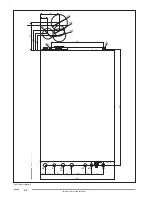
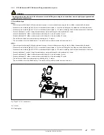
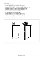
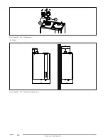
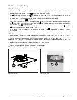
The boiler is equipped with a tower allowing for air intake/flue gas venting pipe connection (see Fig. 13 Plugs position and Fig. 14 Hole
position).
The tower is designed with two pre-arranged openings directly accessing air and flue gas ducts (see Fig. 14 Hole position).
Remove caps A and B from the pre-arranged openings on the tower, before starting combustion checking procedure (see. Fig. 13 Plugs
position).
In order to verify combustion efficiency the following measurements must be implemented:
• assess combustion air from opening 1 (see Fig. 14 Hole position).
• assess flue gas temperature and CO2 from opening 2 (see Fig. 14 Hole position).
Allow boiler to reach working temperature before taking any measurement.
A-B
Fig. 13 Plugs position
2
1
Fig. 14 Hole position

