iTuner Manual
25
Two commands, ADAPTER and TERM, are available to define the s-parameter of these sections,
for both the primary and all secondary frequencies.
Figure 4.2 shows a typical setup where the tuner is located at the input of the DUT. In this
configuration, the adapter is located between the output port of the tuner and the input at the
DUT, and the termination is the source impedance seen by the tuner input.
Output
signal
DUT
Tuning
Reference
Plane
iTuner
Signal
Source
Adapter
SPAR?
GAMMA?
VSWR?
SOURCE
LOSS?
Figure 4-2: Mode SOURCE
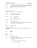
The SPAR? Command returns the s-parameter of the tuner and the adapter.
The loss calculation depends on the current mode setting of the tuner:
MODE LOAD: loss calculation based on Power Gain definition (see figure 4.1)
where
Sij = s-parameter of tuner & adapter
and


