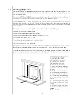
Focal Point JEMEZ Скачать руководство пользователя страница 13

SPARK FAILURE

The gap between the spark electrode and the pilot should be 3.5 - 4.5mm to produce a good spark. There should
be no need to adjust this. If under any circumstances the electric spark fails, the pilot may be lit manually by
proceeding with the ignition sequence as previously described, and after turning the control knob through the
spark position, the knob should be held in and the pilot lit with a taper.

SETTING PRESSURE

The test point is located either on the main injector pipe or 
on the front of the gas valve (marked 

‘out’

) accessible by

removing the control plate. Attach a U gauge and light the fire
on the high setting.

The setting pressure should be in accordance with the figures
stated on page 2 of these instructions. The fire is factory set to
achieve these pressures, and any significant variation could
indicate a supply problem.

If the pressure is too high, the gas supply meter may be set
incorrectly. This should be checked with the fire running and if
necessary reset by the gas supplier.

If the pressure is too low, then check the meter governor pressure with the appliance running. If this is incorrect
it will need to be reset by the gas supplier.

If the setting pressure is too low, but the meter pressure is acceptable, then a problem in the supply pipework is
to be suspected. This will be dirt and debris, kinked or inadequate size pipes, restriction in a fitting or solder
flashing across a joint.

FLUE SPILLAGE MONITORING SYSTEM

This fire is fitted with a flue spillage safety device (ODS). If the fire shuts down during use for no apparent reason
then several things may be suspected. If a door or window has been opened creating a draught, then pilot
disturbance is the problem, and removal of the draught should resolve this. The gas pressure reaching the fire
must also be checked (again, recall your installer to check and rectify any problem). The thermocouple
connection into the back of the gas control valve may also have worked loose during installation, simply get the
installer to tighten.

If pilot disturbance is not the cause, then the ODS safety system may be in operation. Switch the appliance OFF,
check the flue and carry out any remedial work required. Relight the fire and carry out a spillage test. DO NOT
allow the appliance to be used if it continues to fail a spillage test.

The aeration hole of the pilot must be carefully cleaned out on each annual service to ensure continued function
of the ODS.

The spillage monitoring system shall not be adjusted, modified, or put out of operation by the installer. Any spare
parts fitted MUST be of a type supplied for the purpose by the appliance manufacturer.

If the fire is not spilling, then further guidance should be sought, using the Troubleshooting section as a guide.

11

11.2

11.3

12.0

Содержание JEMEZ

Страница 1: ...instructions must be handed to the user for safekeeping Revision B 11 03 Country s of destination GB IE Focal Point Fires plc Avon Trading Park Christchurch Dorset BH23 2BT 01202 499330 Fax 01202 4993...

Страница 2: ...a competent person in accordance with Gas Safety Installation and Use Regulations 1998 It is strongly recommended that a CORGI registered engineer be used for this purpose Read all these instructions...

Страница 3: ...stalled in accordance with the rules in force and used only in a sufficiently ventilated space Consult all instructions before installation and use of this appliance This appliance is free from any as...

Страница 4: ...must be connected to only one fireplace and the flue must not vent more than one appliance i e not shared with a gas back boiler There must be no opening in the flue apart from the one that the appli...

Страница 5: ...to BS 715 Pre cast block flue complying with BS 1289 Any existing under grate draught device must be sealed off The opening wall must be non combustible The appliance requires a hearth with non combu...

Страница 6: ...BEEN PREVIOUSLY USED FOR A SOLID FUEL OR OIL BURNING APPLIANCE X Dimension 60mm VENTILATION No purpose provided ventilation is normally required for this appliance The requirements of other appliances...

Страница 7: ...allow plugs and screws to secure installation It is important that the sealing requirements of the appliance are met at all times and that the flue box is well sealed to any back or infill panel Note...

Страница 8: ...milar Place the coals ceramics and fixings safely to one side Remove the burner from the assembly by removing the two screws in the data control plate Lift away the plate and remove the two screws ret...

Страница 9: ...ame or base and relevant points in the opening or on the wall Rawlplugs will be required NOTE Plastic rawlplugs are not suitable for this application Gas supply Following preparation for the fixing me...

Страница 10: ...ill prevent proper installation after servicing Coil up the surplus cable and tuck the coils out of the way as suggested in the photograph FITTING THE BURNER TRAY Important Note Check that the thermoc...

Страница 11: ...the supports in the matrix over the top of the holes Ensure the coals are not turned sideways such that they actually enter the holes Finally place the rear row of two coals Note The coals must not b...

Страница 12: ...he gas supply up to the fire for any leaks in accordance with current Approved Codes of Practice ACOPs OPERATING THE APPLIANCE The pilot is visible through the left hand side of the matrix Rotate the...

Страница 13: ...is to be suspected This will be dirt and debris kinked or inadequate size pipes restriction in a fitting or solder flashing across a joint FLUE SPILLAGE MONITORING SYSTEM This fire is fitted with a fl...

Страница 14: ...rried out at least one annually Advise that cleaning of the fire may be achieved when the fire is cold using a damp cloth and mild detergent on most surfaces Scratched and other superficial damage to...

Страница 15: ...p ceramic components in plastic bags and dispose at proper refuse sites as directed Re fit the coals by referring to the relevant section of these instructions DISMANTLING THE BURNER TRAY Remove the t...

Страница 16: ...frame and if necessary replace Refitting of the convector box is as described in the fitting section of these instructions PILOT ASSEMBLY Remove the burner tray as in relevant section and pilot unit a...

Страница 17: ...uns for a time and then cuts off Excessive room draught or flue pull rectify Loose or faulty thermocouple rectify ODS system in operation Firebox grommet seal not fitted rectify Lint in pilot aeration...

Страница 18: ...ung children the elderly or infirm are concerned Combustible items such as flooring and furniture and soft wall coverings such as blown vinyl or embossed paper may discolour if fitted too close to the...

Страница 19: ...irements this will have been carried out by your CORGI registered installer For Republic of Ireland ventilation may be required see IS 813 ICP3 IS 327 and any other rules in force OPERATING INSTRUCTIO...

Страница 20: ...ed using a vacuum cleaner or dry cloth Heavy stains may be removed by using a damp cloth and mild household detergent Brass parts of the firefront may be cleaned using a suitable brass cleaner Replace...

Отзывы: