background image

Operating Manual BKS015


26.11.2018


31 


10


Parameter Setting via a PC 

The BKS015.EIP web guide controller can be embedded in an Ethernet network and 
the parameter setting can be done over this network by means of a web browser 
(Internet Explorer 7). The devices have a static IP-address that can be set over the 
user interface. The IP-address is not automatically received over DHCP. 

The parameter setting can also be carried out with a desktop- or laptop computer 
via a peer-to-peer connection (see chapter 8.2) 

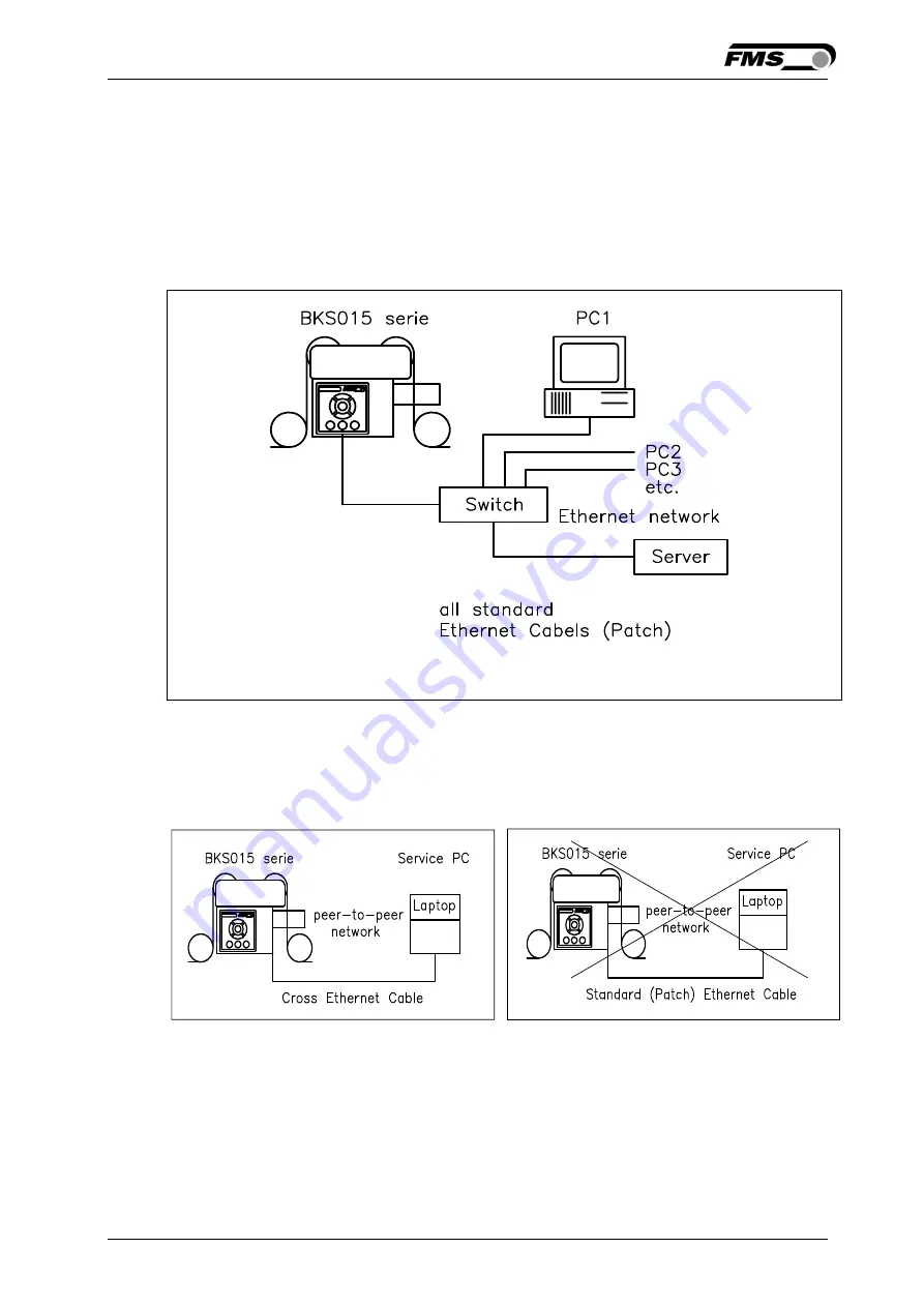
Fig. 20: BKS015.EIP configuration in a LAN (Local Area Network). 

K015009e 


Fig. 21 and 22 show the peer-to-peer connection between PC und BKS015.EIP. Use 
for this configuration a cross-over-cable and not the standard patch Ethernet cable 


10.1


Parameterization in a Network via Web Browser 

Before the parameterization of the BKS015.EIP is done it must be certain that the 
BKS015.EIP uses an IP address in a static block. For the integration of a BKS15 


Fig 22: Connection with wrong cable  
 

K05011e 


Fig. 21: Correct connection with cross-
over-cable. 

 K015010e 

Содержание BKS015.EIP

Страница 1: ...ntroller with EtherNet IP Interface Version 2 14 11 2018 NS Firmware Version V2 21 Diese Bedienungsanleitung ist auch in Deutsch erhältlich Bitte kontaktieren Sie Ihren nächstgelegenen FMS Vertreter by FMS Force Measuring Systems AG CH 8154 Oberglatt All rights reserved ...

Страница 2: ...over EtherNet IP 12 6 1 EtherNet IP Specification 12 6 2 Controller Functionality over EtherNet IP 12 6 3 Integration of BKS015 EIP in an Ethernet Network 12 6 4 Configuration of the Web Guide Controller over EtherNet IP 12 7 Integration in an Allen Bradley PLC 14 7 1 Hardware Environment 14 7 2 IP Configuration 14 7 3 Integration in a Project 14 7 4 Access to the Status Information 17 8 Operation...

Страница 3: ...6 11 2018 3 10 Parameter Setting via a PC 31 10 1 Parameterization in a Network via Web Browser 31 10 2 Parameterization via a PC peer to peer connection 35 11 Dimensions 39 12 Trouble Shooting 41 13 Technical Specification 42 ...

Страница 4: ...s only guaranteed with the recommended application of the components In case of other arrangement heavy malfunction can be the result Therefore the installation instructions on the following pages must be followed strictly Local installation regulations are to preserve safety of electric equipment They are not taken into consideration by this operating manual However they have to be followed stric...

Страница 5: ...frame is activated by a stepper motor The rollers are manufactured and balanced according to customer specification End positions are controlled by hall sensors The material sensors are mounted on the lower frame by means of a bracket array and are easily adjustable to the web width 2 3 Web Guide Controller The micro processor based electronic control unit handles all calculations and communicatio...

Страница 6: ...on Industrial Protocol The web guide controller can be embedded in a standard Ethernet infrastructure Its fast data rate with cycle times down to 2ms makes the device ideal for applications in automated assembly and production lines Configuration of the web guide controller takes place either over the EtherNet IP a web browser or over the operating panel Fig 2 BKS015 EIP in an Ethernet Network K30...

Страница 7: ...P and chapter 4 4 Connector and Screw Terminal Arrangement 4 If required determine special parameters ref to 7 1 Description Operation Parameters 3 2 Installation Procedure 1 Mount and ajust your material sensor s to the steering frame ref to chapter 4 2 2 Mount the web guide to the machine frame 3 Connect the sensor s to the electronic unit 4 Make sure the power supply voltage is in the range 18 ...

Страница 8: ... the machine frame The machine must be prepared to accept the M5 mounting screws The steering frame must be connected to earth ground Ensure that the base plate of the steering frame has direct contact with the grounded machine frame In addition the ground bolt see Fig 1 must be connected to the machine earth Caution Bad earth connection may cause electric shock to persons malfunction of the total...

Страница 9: ...frame Caution Make sure that the sensor s are connected properly to the electronic unit by means of the delivered orange cables For left right orientation please refer to Fig 3 If the connections are crossed over malfunction can be the result 4 3 Connecting the BKS015 EIP The power supply unit musst deliver a voltage from 18 to 36V DC Vnom 24V Connect the cable coming out of the PG gland to your p...

Страница 10: ...Operating Manual BKS015 26 11 2018 10 Fig 4 Terminal arrangement on processor board K015008e Note An Ethernet connector RJ 45 is also available on the back side of the housing ...

Страница 11: ... VDC Vnom 24V 2 Check if the web is in the detection range of the sensors 3 Switch on your power supply 4 The web guide starts up in Manual Operating Mode 5 2 Adjustment of the Sensors Align sensor axis to the web edge Loosen the fixing nut on the bracket and adjust the sensor Fix the sensor in the new position The sensor will be properly positioned if the web edge goes through the sensor axis cen...

Страница 12: ...ress must be assigned in the fix address block and must be unambiguously It may only exist once in the network The network mask must correspond with the used device configuration If these prerequisites are given the controller will recognise the amplifier as an EtherNet IP device in the network and be able to communicate with it The interface information for BKS015 EIP is defined in an EDS file Th...

Страница 13: ...ibed in the example project The example project BKS309_BKS015_EIP_Example_Project_Vx xx is available for download on the FMS website Note The configuration of the web guide controller via EtherNet IP must be used as commissioning procedure Continuously writing parameters on a cyclic base is not allowed and will lead to communication problems and reduced the lifetime of the device ...

Страница 14: ...tion between BKS015 EIP and PLC can take place Several BKS015 EIP or other ErtherNet IP devices can be connected to the same network 7 2 IP Configuration In an industrial environment the IP addresses are normally assigned fix to the EIP devices This holds also for the BKS015 EIP controller that needs a fix IP address in the network The IP address configuration must take place before the BKS015 EIP...

Страница 15: ...nt hardware is used one may find the listing Ethernet in another place However the principal approach is always the same After a right mouse click on Ethernet a dialog window will open up Left mouse click on New Module and a new window will open up see Fig 7 Fig 6 Controller Organisation K309EIP02 ...

Страница 16: ...ing window opens up in which the Name BKS309_91 the Comm Format Input Data DINT and the IP Address eg 192 168 0 91 need to be entered On the Connection Parameters side the values Input 100 with Size 2 Output 101 leave empty and Configu ration 102 with Size 88 must be entered Confirm with OK Fig 7 Module Selection E309022 Fig 8 Module Selection open E309023 Fig 9 New Module K309EIP03 ...

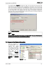
Страница 17: ...necks Especially when using several BKS309 and other EIP devices in the same network a well balanced data speed is important Fig 10 Module Properties Note Untick the box Use Unicast Connection over EtherNet IP The use of this feature is not allowed as it will cause communication problems 7 4 Access to the Status Information After the integration of the BKS015 EIP in the network the status informat...

Страница 18: ...urther actions Bit 0 set Automatic Operation switched on Bit 1 set reserved Bit 2 set reserved Bit 3 set Web Guide or winderGLIDE actuator locked Bit 4 set Web Guide or winderGLIDE actuator was driven to the center Bit 5 and Bit 6 are not set Left edge guiding Bit 5 set and Bit 6 not set Right edge guiding Bit 5 and Bit 6 are set Centre guiding ...

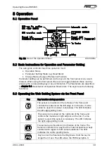
Страница 19: ...ing functions 8 3 Operating the Web Guiding System via the Front Panel Key Key function during operation The sensor is mounted on the left side of the frame and controls the material on the left edge or on the line if a line sensor is used One sensor is necessary The LED indicates the left edge guiding mode The sensor is mounted on the right side of the frame and controls the material on right edg...

Страница 20: ...nuously move the Reference Position to the left see chapter 8 4 Operation in Automatic Mode In parameter setting mode Pressing the button reduces continuously the parameter value In manual mode the frame will move to the right in 0 1mm steps by pressing the button once By pressing the button longer than 1 sec it will continuously move the frame to the right In automatic mode the Reference Position...

Страница 21: ...eps by using the and keys For left sensor operation the key causes the web moving inside the sensor The key causes the web moving outside the sensor Using right sensor operation or center guiding the setting behaves contrariwise refer also to Fig 17 18 and 19 Terminate the automatic mode by using the key again Caution If web is not running it can t be guided properly to the Reference Position The ...

Страница 22: ...an only be entered in Manual Operation 8 6 Entering the Parameter Setting Mode To enter the Parameter Setting Mode the web guide controller must be in the Manual Mode In the Automatic Mode only the reference value can be changed Press the key for longer then 3 sec The LED above the key will light indicating that the controller entered the Parameter Setting Mode In this mode the Dead Band parameter...

Страница 23: ...d values K015005e c Setup mode for the adjustment of the Reference Position for left sensor operation Setup is only possible in automatic mode with the direction keys Fig 10 LED indication of Reference Position values left sensor K015013e d Setup mode for the adjustment of the Reference Position for right sensor operation and center guiding Setup is only possible in automatic mode with the directi...

Страница 24: ...Operating Manual BKS015 26 11 2018 24 8 8 Sensor Detection Range and Reference Position Fig 19 View of the Sensor Detection Range K015007e ...

Страница 25: ...e Reference Position is kept stored until the next power on Range 5 0 to 5 0 Default 0 0 Increment 0 1 Unit mm Note By pressing the keys and at the same time for longer then 1 sec the Reference Position will reset to default Setting Reference Mode Ref Mode Purpose This parameter determinates how the Reference Position is defined This can either be the position that is defined with parameter Ref Po...

Страница 26: ...efault value Unit System Unit Sys Purpose This parameter determines the unit system that is used when the parameters are set via the web browser The user can choose between two settings Setting Metric Purpose Settings in the web browser are carried out in metric units Setting Imperial Purpose Settings in the web browser are carried out in imperial units Gain Setting Gain Purpose This parameter def...

Страница 27: ...the behaviour of the controller leaving the automatic mode The user can choose between two behaviours Setting Manual Purpose The controller stops guiding The web guide is locked at the current position Manual Mode Setting Centre Purpose The controller stops guiding Afterwards the web guide moves to the centre IP Addr Purpose The parameter assigns an IP address to the controller This enables the us...

Страница 28: ...ettings and should not be changed without contacting the service department of FMS An unauthorised change can cause malfunctions in the system or damage in the machine Offset Centre Offset Purpose This parameter adjusts the position of a steering frame exactly to the centre Type One Hall Purpose One hall sensor is used to detect the Home position Middle Position and Maximum Position Type Two Hall ...

Страница 29: ... 2018 29 measured from the left reference position The actuator stops at this position if you press the centre key In Automatic Operation this parameter has no meaning Range 0 to 10 000 Default Factory setting Increment 1 Unit Step ...

Страница 30: ...ncrement 1 Unit Step Drive Direction DriveDir Purpose This parameter determines the guiding orientation of the controller Usually stepper motors turn clockwise This setting changes the turning direction of the motor There are two other possibilities to change the guiding direction The user can choose between two settings Setting Standard Purpose Standard is chosen when standard motors and standard...

Страница 31: ...t with a desktop or laptop computer via a peer to peer connection see chapter 8 2 Fig 20 BKS015 EIP configuration in a LAN Local Area Network K015009e Fig 21 and 22 show the peer to peer connection between PC und BKS015 EIP Use for this configuration a cross over cable and not the standard patch Ethernet cable 10 1 Parameterization in a Network via Web Browser Before the parameterization of the BK...

Страница 32: ...m administrator Once the BKS015 EIP was integrated in the network you can address the device e g with http 192 168 000 090 After establishing the link the screen Fig 23 will open up Fig 23 Serial number and device information Home jpg The menu on the left side of the screen allows navigating through the web page ...

Страница 33: ...Operating Manual BKS015 26 11 2018 33 Fig 24 Front panel for remote control purposes Remote Control Fig 25 Parameter list Parameters can be changed Parameters ...

Страница 34: ...Operating Manual BKS015 26 11 2018 34 Fig 26 Ethernet settings and device addresses Ethernet Settings ...

Страница 35: ... with FMS BKS015 EIP web guide controller Before connecting the FMS BKS015 EIP controller with a cross over cable directly to a PC the computer must be configured with a static IP address that lets it recognize the BKS015 EIP If the BKS015 EIP controller is connected to a network by using e g a switch the following procedure is not necessary To establish the connection between your PC and the BKS0...

Страница 36: ...rt button lower left hand corner of the screen 2 Click on Control Panel 3 Double click on Local Area Network 4 Right click on the network adapter that is used for the connection 5 Click on Properties on the pop up menu the following dialog box Local Area Connection Properties will appear ...

Страница 37: ...nnection uses the following items scroll down to Internet Protocol TCP IP Select the Internet Protocol TCP IP and click Properties The following dialog box will appear Make sure the General tab is selected Select the radio button Use the following IP address ...

Страница 38: ... for the computer that could be 192 168 0 1 In the Subnet mask enter 255 255 255 000 as shown below Notice that the 000 in both boxes will change automatically to 0 The dialog box will change to look like the following Click the OK button The following dialog box will appear again ...

Страница 39: ...orer or Mizilla Firefox 3 The default IP address for the BKS015 EIP is 192 168 000 090 as long as it was not changed over the operating penal Enter the IP address in the address bar and hit the Enter key If a different IP address and subnet mask is configured at the BKS015 EIP make sure that the computer is setup appropriate 4 The screen Fig 23 will open up Continue then with the procedure describ...

Страница 40: ...Operating Manual BKS015 26 11 2018 40 250mm The mechanical dimensions can be seen in the following drawing Fig 28 Outline Drawing BKS015 EIP K015002 ...

Страница 41: ...Steering frame does not move No signal sensor not correctly connected Connect sensor correctly according to screw terminal arrangement and installation guide No signal cable interruption Replace cable or send sensor to FMS No signal sensor defect Send sensor to FMS use other sensor No response of the interface Wiring not correct Check wiring LED row shows nothing frame doesn t react Fuse blown Rep...

Страница 42: ...band 0 2mm adjustable in 0 1mm steps Position reference 5mm adjustable in 0 1mm steps Control modes edge left edge right center guiding Interface Web browser Ethernet Explorer 7 or higher Operation 3 keys and 5 key wind rose pad Analogue inputs 2 inputs 0 10V for sensors Supply voltage 24 18 to 36 VDC Temperature range 10 to 60 C 14 to 140 F Protection class IP 30 ...

Страница 43: ...Operating Manual BKS015 26 11 2018 43 ...

Страница 44: ...echnology com www fms technology com FMS USA Inc 2155 Stonington Avenue Suite 119 Hoffman Estates IL 60169 USA Tel 1 847 519 4400 Fax 1 847 519 4401 fmsusa fms technology com FMS UK Aspstrasse 6 8154 Oberglatt Switzerland Tel 44 0 1767 221 303 fmsuk fms technology com FMS Italy Aspstrasse 6 8154 Oberglatt Switzerland Tel 39 02 39487035 fmsit fms technology com ...

Отзывы: