


Doc. No.: OMS500000104
Rev: A Page 31 of 42
Subject to contractual terms and conditions to the contrary, this document and all the information contained herein are the confidential and exclusive
property of FMC Technologies, and may not be reproduced, disclosed, or made public in any manner prior to express written authorization by FMC.
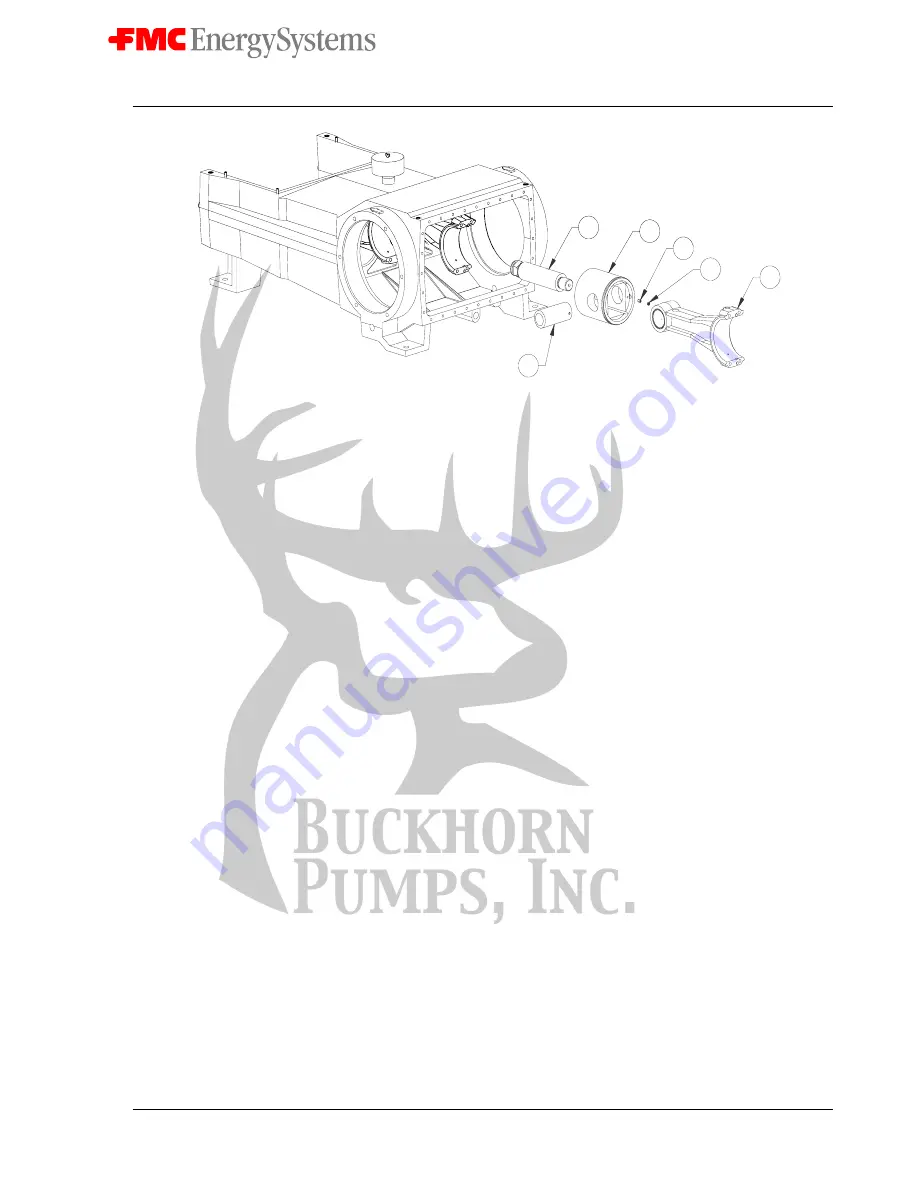
6
5
22
21
3
4
Figure 11: Cross Head and Con Rod Removal
14. Thoroughly clean all parts with solvent and apply a thin coat of oil before reassembly.
15. Tapered roller bearing cones must be heated to aid in assembly to the shaft. Always
observe proper safety procedures and use heat resistant tools and gloves when handling
hot parts. There are a number of recommended methods for heating bearings. Electric
ovens or electrically heated oil baths may be used, but only when accompanied by proper
thermostatic control.
16. To replace the crankshaft (2) tapered roller bearings, heat the cones to a maximum of
300
°
F and slide down the shaft unit it is full seated against shoulder. The hot cone (12)
may pull away from the cold shoulder unless it is held in position until it cools enough to
grab the shaft. Use a .001” thick feeler gauge to insure the cone (12) is fully seated
against the shoulder after parts have cooled.
17. Use a press to seat the new cups (11) in the bearing housing (7 & 8). Never use new
bearing cones (12) with old bearing cups (11).
18. Reassemble the crosshead assemblies (5) and connecting rods (3). Install new rod
bearing inserts (13). Insure that the set screws (21 & 22) retaining the wrist pins (4) are
in place if they were removed for repair or inspection of the wrist pin bushing.
19. Push the crosshead assemblies fully forward in power frame (1) to provide maximum
clearance for the crankshaft (2). Insure crosshead assemblies (5) are replaced in same
orientation and in the same cylinder bore they were originally. The oil cup pocket
feeding lubricant to the wrist pin bushing is on the top of the connecting rod (3) and
should be in the up position.
20. Install crankshaft (2) in the power frame (1). Take care not to scratch bearing surfaces of
the crank (2). Again tool P517959 (A) is very helpful for this purpose due to the weight
of the crankshaft (2).
21. Reinstall the shims (9) and bearing housings (7 & 8). As a starting point, install the same
number of shims (9) that the pump originally had prior to service. Inspect the o-ring (24)
that seals the bearing housing (7 & 8) and replace it if damaged.