FMA Direct
5
Co-Pilot II reference manual
Mounting on an airplane
Typical mounting locations for the Main Sensor Module include
on the top or bottom of the fuselage, on top of the wing of a
high-wing airplane, or on the bottom of the wing of a low-wing
airplane.
Main sensor module mounted on bottom of fuselage
The photo on the previous page shows the Main Sensor Module
mounted on the bottom of the fuselage of an electric airplane.
This would not be a good location on a fuel-powered airplane, as
it would expose the Sensor to exhaust.
Mounting on a helicopter
The Main Sensor Module is typically mounted on the tail boom,
rotated 45°, and located in the center of the boom so the forward
facing IR sensors have a clear view of the horizon. Here is the
recommended installation procedure:
1. Cut the corners from the plastic mount (diagonal cutters can
do this quickly).
Plastic mount after corners cut off (bottom view)
2. Place double-sided tape on the boom about halfway between
cockpit and tail. Place the plastic mount on the tape and se-
cure it to the boom using a cable tie (the double-sided tape
keeps the plastic mount from rotating).
Tip:
The Main Sensor Module can be mounted above or below
the boom. Mounting the Module below the boom may help pro-
tect it in the event of a boom strike.
3. Use double-sided tape to secure the Main Sensor Module to
the plastic mount. The Sensor Module should be rotated 45°
relative to the boom (i.e., two Sensor Module corners pointing
fore and aft). Typically, sensors 2 and 3 will face forward so
the cable routes forward along the boom.
Tip:
For additional security, feed cable ties through the slots in
the bottom of the Sensor’s case and around the boom.
Main Sensor Module mounted on top of helicopter boom
Mounting the Vertical Sensor Module
The Vertical Sensor Module can be mounted anywhere on the
aircraft, as long as the following requirements are met:
n
Must be vertical when the aircraft is in level flight.
IMPORTANT:
The arrow on the Vertical Sensor Module must
point to the sky when the aircraft is in level flight. Failure to follow
this precaution may result in unexpected results and a crash.
n
Must be at least 6 inches from the Main Sensor Module so that
the Main Sensor Module’s IR sensors are not obstructed.
n
On fuel-powered aircraft, should be at least 12 inches from the
engine and muffler, in a location where exhaust will not accu
-
mulate on the IR sensors during flights.
If needed, use a standard servo extension to connect the Vertical
Sensor Module to the Computer.
Mounting on an airplane
The Vertical Sensor Module is typically mounted on the side of
the fuselage.
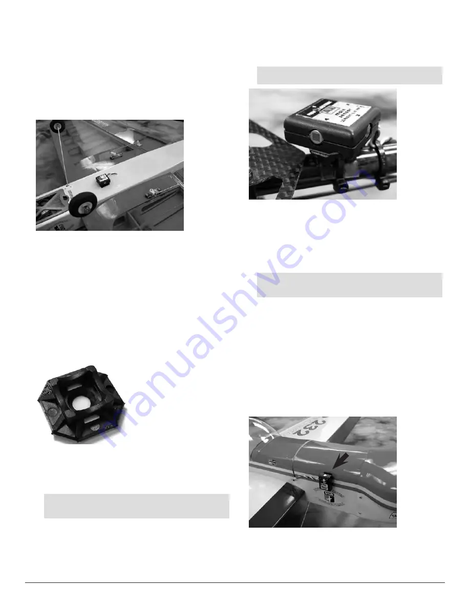
Vertical Sensor Module mounted on fuselage side
The photo above shows the Vertical Sensor Module mounted on
the right side of the fuselage, in front of the wing, on an electric
airplane. This would not be a good location on a fuel-powered
airplane, as it would expose the Sensor to exhaust.


