background image

Figure 4.33: Airspace Settings Example

4.7.14 GPS status

In the main menu the GPS SD provides a detailed view of the GPS status,the current position dilution of

precision (pdop) value ,and the current GPS coordinates of the pilot.

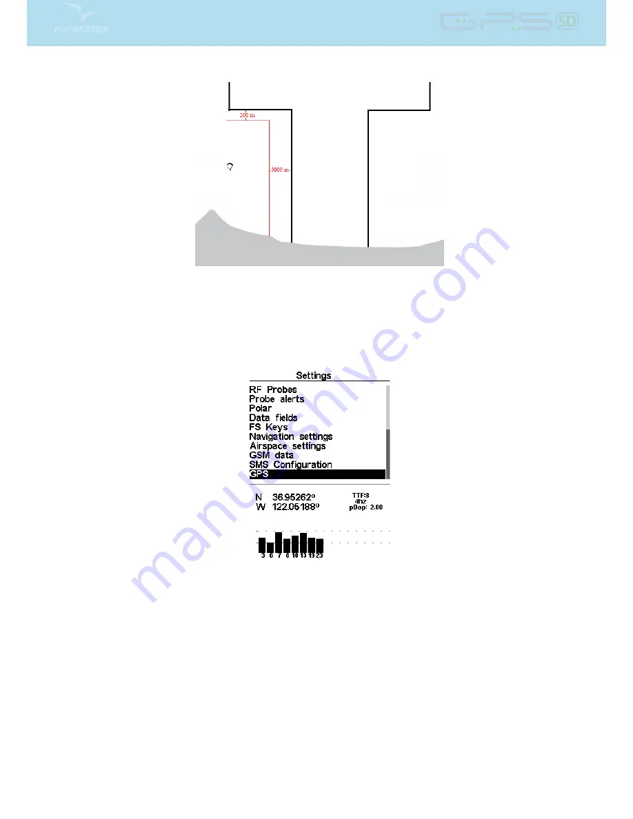
Figure 4.34: Satellite status

Figure

4.34

illustrates the GPS satellite reception page. In this example the GPS SD shows that 8 satellites

are visible, and all 8 are being used to provide the position x. Each bar shows the signal strength for each

individual satellite. A lled bar indicates the GPS SD has a lock on that satellite. The position dilution

of precision (pdop) shown gives an indication of how reliable the GPS data is at the moment. The lower

the pdop value the more accurate the position x. Values bellow 2.5 are fairly accurate. If the GPS SD is

switched on in a location where no satellites are visible (indoors for example) it will go into wide search

mode. If this occurs, going outdoors again will make the GPS SD take an increased amount of time to

pick up satellite signals. If this occurs pushing ENTER on the GPS menu item will reveal the Reset GPS

option, changing it to yes will make the GPS SD reset the GPS status and start a new search (see Figure

4.35

). So if you notice GPS SD is taking abnormally long to get a x (over 2 minutes) a gps reset will

probably get it locked quicker.

44

Содержание GPS SD

Страница 1: ...User manual Document version 1 0...

Страница 2: ...ionics re serves the right to change or improve its products and to make changes in the content without obligation to notify any person or organisation of such changes or improvements Visit the Flymas...

Страница 3: ...attery 8 3 1 2 Sound 8 3 1 3 GPS 9 3 1 4 Vario 9 3 1 5 Navigation Circle 11 3 1 6 Airspaces Map 12 3 1 7 Altitude graph 14 3 1 8 Wind Arrow 14 3 1 9 Map Page 15 3 2 Data eld Elements 16 4 Menu mode 21...

Страница 4: ...erts 41 4 7 11 Polar 42 4 7 12 FS Keys 42 4 7 13 Airspace settings 43 4 7 14 GPS status 44 5 RouteDe nition 46 5 1 Route De nition 46 5 2 Setting up the route 46 6 McCready Functions 47 7 Firmware 48...

Страница 5: ...information is shown on both the power up screen and the Shutdown menu When the Flymaster GPS SD is connected to a power supply wall charger or via USB cable even with the unit o the instrument will...

Страница 6: ...d DOWN keys changes the value on each eld Pushing the ENTER key moves to the next eld or in same cases to the next character digit Conversely pushing MENU key moves to the previous eld or to the previ...

Страница 7: ...de ned FS Key will scroll up the sound level until the maximum value Pressing more will mute the sound before start scrolling again starting from the minimum value Note Changing the volume using an FS...

Страница 8: ...ed by the user using a free application called Flymaster Designer which can be downloaded from the Flymaster website www ymaster net This intuitive tool allows the user to create an unlimited number o...

Страница 9: ...raphical indication of the current battery level In Table 3 1 it is possible to see the relationship between what is shown and the actual battery level in percentage This element has xed dimensions Ta...

Страница 10: ...PS update rate most of others only provide 1Hz which allows the GPS SD pilot to see very small speed and position changes Furthermore the movement of the direction arrow is smoother and any position c...

Страница 11: ...he Double Bar Analog Vario element shows not only the instantaneous vertical speed but also the Average Thermal and Next Expected Thermal McCready Indicator see Figure 3 3 This element can be resized...

Страница 12: ...ure 3 5 Navigation Element Navigation information is shown within the inner most circles The external circle contains the cardinal points and the Wind Flag The current traveling direction bearing corr...

Страница 13: ...l core is constantly updated as the pilot moves When the pilot is over 300m from the thermal core the dot will be at the edge of the circle As the pilot moves closer to the thermal core the dot will m...

Страница 14: ...he pilot is inside the airspace then a black line is used instead Note that being inside a airspace area 2D does not mean that the airspace is being violated since the pilot can be above or below the...

Страница 15: ...s a plot of the absolute barometric altitude over the last 4 minutes of ight Figure 3 12 Figure 3 12 Altitude Plot 3 1 8 Wind Arrow The Wind Arrow element Figure 3 13 is a re sizable graphical element...

Страница 16: ...ed around the screen Figure 3 15 Map Element A typical map page in ight may look like Figure 20 In this gure is shown the scale on the bottom left The scale can be manually changed by pressing the F1...

Страница 17: ...g i e airspace that you are violating or close to violating Floor Shows the lower altitude of the airspace causing the warning i e airspace that you are violating or close to violating Time Current lo...

Страница 18: ...s we must sink to come out of controlled airspace CTR Status Status message of airspace will show Violating when in controlled airspace Immenent Alt when close to entering airspace vertically or Pos I...

Страница 19: ...eedToFly Optimal Speed to Fly value calculated according the McCready Theory The True Air Speed value is calculated based on the de ned polar and the average thermal speed McRdyNxtThrm Next thermal ex...

Страница 20: ...l Fuel level in liters available when connected with Flymaster M1 Arrival Next Estimated arrival height above the next waypoint This means that wind day quality and glider performance are used in the...

Страница 21: ...te The GPS SD considers a thermal has been entered when the integrated vario value is above 0 5m s and considers the thermal as been exited when the integrated vario goes bellow 1 0 m s Once in the th...

Страница 22: ...Accesses GPS SD s waypoints and Routede nitions see Section 4 1 RouteNavigator Allows manual override of navigation Critical Airspaces This page constantly shows the airspaces which are closer than t...

Страница 23: ...instrument1 The rst waypoint on the list appears highlighted and the corresponding data of the selected waypoint is shown in the DO area As the cursor is moved to a di erent waypoint so the data chan...

Страница 24: ...the Route select the waypoint that is to be added by pressing either the UP or DOWN buttons until the desired waypoint is highlighted Pressing the ENTER button will add the point onto the TL on the ri...

Страница 25: ...o the Waypoints Routewill cancel the active Go To The Go To function will override the Routenavigation although the GPS SD will remember where it was in the Route so when the Go To is canceled as desc...

Страница 26: ...DOWN buttons move the task point to the desired position and push ENTER Remove Route Point To remove a task point select it using UP and DOWN buttons and then pushing the ENTER button to activate the...

Страница 27: ...he altitude and distance threshold is set to 200 meters then all the airspaces that are closer from the pilot s position than 200 meters are shown on the Critical Airspaces list A typical list of airs...

Страница 28: ...ssary glide ratio to reach it is 9 6 The Nearby Landings page can also be used to make a Go To Use the UP and DOWN keys to select the desired waypoint then push the ENTER key to immediately activate n...

Страница 29: ...ght Distance Distance own Pushing the ENTER key will display the Flight Log Action List with options Delete ight Delete all ights Each of the options is explained in the following sections Also if you...

Страница 30: ...hout data from Flymaster accessories like HEART G or TASProbe which equates to over 36 hours with a 1 second recording interval obviously if you set it to a 10 second recording interval you get 360 ho...

Страница 31: ...You can select di erent pages by selecting either the UP or DOWN keys If you press ENTER for a certain page 2 options become available as shown in Figure 4 13 Figure 4 13 Page Options Selecting the Go...

Страница 32: ...will be on the Enable Page Pressing ENTER will re enable the page 4 7 Settings Menu The Settings Menu is used to con gure the GPS SD s many features The menu screen is divided into two sections On th...

Страница 33: ...ltimeter can be achieved by entering the know altitude of the location Entering an altitude automatically calculates the QNH which is the local barometric pressure adjusted to sea level Alternatively...

Страница 34: ...a turn point cylinder See Section 4 5 about track log memory capacity UTC o set Using GPS data the GPS SD automatically adjusts the internal clock to the Universal Coordinated Time UTC The user shoul...

Страница 35: ...be set from 500 to 1500 Hz The higher is the frequency value the higher pitched the sound is In order to change the base frequency value press the ENTER key after the Audio Frequencies menu option is...

Страница 36: ...parameter speci es which cadence curve should be used Current there are 2 possibilities represented in the graph of Figure 4 21 Figure 4 21 Cadence timing Dynamic Frequency The GPS SD beeps at a speci...

Страница 37: ...nding at 0 2 m s At this stage the orange pilot starts to hear the Buzzer brrrrr sound of his GPS SD which helps him to center the thermal while the green pilot is still unaware of the thermal Finally...

Страница 38: ...rey lines Set Yes the trace lines in lift will be drawn in black while the sink will be drawn in grey Set to No and all the trace lines will be drawn in black Track up Track up allows the trace to be...

Страница 39: ...t and to the left to decrease the contrast When in the desired position push the ENTER key to con rm the value WARNING Beware of adjusting a very low contrast value may cause the display to be totally...

Страница 40: ...sider that page 3 is associated with the trigger Airspace Warning and the current displayed page is page 2 If during ight an airspace limit is reached the device will automatic change the page 3 The c...

Страница 41: ...taken because all changes made by the user are lost Reset now Makes a hardware reset to the instrument The result is the same as the one presented in Section 1 5 Auto o If set to Yes the GPS SD turns...

Страница 42: ...s available 4 7 10 Probe Alerts Figure 4 29 Probe Alerts The GPS SD allows relating alerts with some probes values see Figure 4 29 A short description of each alert is sown in Table 4 6 Table 4 6 Prob...

Страница 43: ...aximum and minimum horizontal speed of the glider The point Between should be some point between the Maximum and Minimum Figure 4 31 Polar 4 7 12 FS Keys In Flight Mode keys UP DOWN and ENTER can have...

Страница 44: ...done by pressing the MENU key As shown in Figure 4 32 there are 5 parameters related to the airspace which are explained in Table 4 8 Table 4 8 Airspace Menu Settings Function Description CTR dist Th...

Страница 45: ...sition dilution of precision pdop shown gives an indication of how reliable the GPS data is at the moment The lower the pdop value the more accurate the position x Values bellow 2 5 are fairly accurat...

Страница 46: ...Figure 4 35 GPS Reset 45...

Страница 47: ...g route on the GPS Then add to the route in the right order T01 W03 W06 The GPS will automatically assume T01 as the takeo since it is the rst waypoint on the list The completed route should look like...

Страница 48: ...he average thermal speed used to calculate the Speed to Fly is manually set by the pilot McCready Ring On the GPS SD this value is calculated by averaging the last thermals climbed Conversely for each...

Страница 49: ...re is no need to install further software Figure 7 1 Firmware Menu Option Once the Designer is correctly installed do the following procedure 1 Open the Designer 2 Select Tools Firmware see Figure 7 1...

Страница 50: ...Figure 7 2 Firmware Update Done 49...

Страница 51: ...stalled on the computer and that GPSDump has been installed 8 1 Con guring GPSDump Before you can start interfacing your Flymaster GPS unit with your computer you must rst make sure that you have set...

Страница 52: ...that are currently interfacing with the instrument Flymaster instruments typically populate with high COM port numbers such as COM 11 in the example below Figure 8 3 Figure 8 3 COM port options Once t...

Страница 53: ...igure 8 4 Waypoint list Once the le has been opened select alll of the waypoints COMMAND A in MAC and CONTROL A for PC In the drop down menu for WPTS you should see the following options Figure 8 5 52...

Страница 54: ...ending the waypoint ID or the waypoint name or both Once you select the type of waypoints to send you should see the the waypoints being sent to the instrument 8 3 Downloading tracklogs To download a...

Страница 55: ...on the instrument Figure 8 7 Figure 8 7 Tracklog list Simply clicking on the desired ight will download the tracklog to the computer Once the tracklog has been downloaded it is possible to save the t...

Страница 56: ...ng 43 Base Frequency 34 Climb Threshold 33 Delete All Flights 29 Delete Flight 28 Flight Log 27 Increments 34 Memory capacity 29 Sink Alarm 34 Sink Threshold 34 Sound Volume 34 Time Setting 33 Volume...

Отзывы: