background image


3.  OPERATION 


Page 77 

© 1995 - 2010 Fluke Corporation, DH Instruments Division   

Table 30.  

Flow Units and Corresponding Total Mass or Volume Units 

FLOW UNIT 

TOTAL MASS OR 

VOLUME UNIT 

mol/s 

mol 

kg/s 

kg 

mg/s 

mg 

slh or slm 

sl 

sccm 

scc 

scfh or scfm 

scf 

Ulm 

ul 

Uccm 

ucc 

ucfm or ucfh 

ucf 

plm or plh 

pl 

pccm 

pcc 

pcfm or pcfh 

pcf 

lm or lh 

ccm 

cc 

m3m or m3h 

m3 

cfm or cfh 

cf 

3.4.6.5 

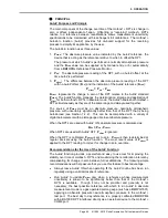
<5Unit> 


PURPOSE 

To activate the UNIT DISPLAY. 

Note 

See Section 3.4.6, PRINCIPLE. 


OPERATION 

To activate the UNIT DISPLAY, press 

[DISPLAY] 

and select

 <5unit>

.  The unit 

of measure that will be used for the second line of the MAIN run screen display 
must then be selected.  The unit selection process is identical to that of the 

[UNIT] 

function key (see Section 3.4.3).  Once the unit has been selected 

operation returns to the MAIN run screen with the UNIT DISPLAY active. 

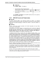
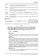
With the UNIT DISPLAY active the MAIN run screen is: 

1. 

Standard MAIN run screen top line. 

2. 

Flow equivalent of the current measured flow in the 
alternate flow unit of measure. 

3. 

Alternate flow unit of measure selected in UNIT 
DISPLAY. 


* 101.27 sccm    N20 

= 0.1013 slm 


 Caution 

The reference temperature setting for the user units (i.e., uccm 
and ulm) (see Section 3.4.3.3) and the temperature and pressure 
settings for volume units (see Section 3.4.3.4) apply to the units 
in the main UNIT selections as well as the UNIT DISPLAY 
selection. Therefore, it is not possible to simultaneously display 
user units or volume units with different reference temperatures 

Содержание MOLBOX1 PLUS S - V 6.00

Страница 1: ...1995 2010 Fluke Corporation DH Instruments Division molbox1 molbox1 S molbloc Terminal Ver 6 00 and Higher Operation and Maintenance Manual...

Страница 2: ...of its published materials however no warranty expressed or implied is provided DH Instruments disclaims any responsibility or liability for any direct or indirect damages resulting from the use of th...

Страница 3: ...1 2 Inspecting Contents 25 2 2 Site Requirements 25 2 3 Initial Setup 26 2 3 1 Preparing for Operation 26 2 3 2 Power Connection 26 2 3 3 molbox1 to molbloc Connections 27 2 3 4 Gas Supply and Flowpa...

Страница 4: ...4 3 4 4 5 5BPR molbloc S Operation Only 69 3 4 5 P T Pressure and Temperature 70 3 4 5 1 molbloc L Operation 71 3 4 5 2 MOLBLOC S operation 71 3 4 6 DISPLAY 72 3 4 6 1 1Rate 73 3 4 6 2 2Avg Average 74...

Страница 5: ...nce Adjustments and Calibration 141 5 1 Product Overview 141 5 2 Calibration Of Reference Pressure Transducers RPTS 142 5 2 1 Principle 142 5 2 1 1 PA and PM Coefficients 142 5 2 2 Equipment Required...

Страница 6: ...sion Page IV 7 Appendix 163 7 1 Conversion of Numerical Values 163 7 1 1 Pressure 163 7 1 2 Temperature 163 7 1 3 Flow 164 7 2 Valve Drivers 166 7 3 MFC Control Function 168 7 3 1 MFC Connector 168 7...

Страница 7: ...in Trifluoromethane at Various molbloc Upstream Pressures 19 Table 19 Air molbloc S Flow in Air at Various molbloc Upstream Pressures 20 Table 20 CO2 molbloc S Flow in Carbon Dioxide at Various molblo...

Страница 8: ...e Providers 171 Figures Figure 1 molbox1 Front Panel 24 Figure 2 Rear Panel 24 Figure 3 molbox1 Internal Pneumatic Schematic CHANNEL A ACTIVE molbloc L OPERATION 33 Figure 4 Keypad Layout 39 Figure 5...

Страница 9: ...towards additional information on a topic Cross references are generally in parentheses and give the reference s section number For example see Section 11 Certain words and expressions have specific m...

Страница 10: ...MOLBOX1 MOLBOX1 S MOLBLOC TERMINAL OPERATION AND MAINTENANCE MANUAL 1995 2010 Fluke Corporation DH Instruments Division Page VIII Notes...

Страница 11: ...e communication capability is supported with RS232 and IEEE 488 interfaces molbox1 is equipped to handle molblocs on two separate channels This allows easy switching between two different molblocs as...

Страница 12: ...calibrated to be used at an absolute pressure which remains nearly constant while the differential pressure varies with flow rate Different operating pressure options and their effect on molbloc flow...

Страница 13: ...ange 20 to 70 C Vibration Meets MIL T 28800D Weight 6 8 kg 15 lb max Dimensions 32 cm W x 12 cm H x 30 cm D 12 6 in x 4 7 in x 11 8 in approx Microprocessor Motorola 68302 16 MHz Communication Ports R...

Страница 14: ...ute 14 5 to 174 psia A2M 100 to 2000 kPa absolute 14 5 to 290 psia Resolution A350K 0 4 Pa 0 00005 psi A700K 0 7 Pa 0 0001 psi A1 4M 1 4 Pa 0 0002 psi A2M 2 Pa 0 0003 psi Accuracy A350K Absolute press...

Страница 15: ...for each molbloc type in section 1 2 5 1 and 1 2 5 2 For both molbloc L and molbloc S elements there are separate performance specifications given for the premium and standard calibration types that a...

Страница 16: ...ted gas for which the molbloc in use is calibrated 0 125 of reading from 10 to 100 FS 0 0125 FS under 10 FS 1E5 molbloc L Premium calibration not available 1 Precision Combined linearity hysteresis re...

Страница 17: ...de SF6 10 50 100 200 500 1 000 2 000 500 6 000 1 000 6 000 4 000 Xenon XE 10 40 80 150 400 800 3 500 500 8 000 11 000 3 000 30 000 20 000 FLAMMABLE Butane C4H1 0 20 100 130 30 270 50 670 140 2 300 2 2...

Страница 18: ...0 2 000 3 700 1 200 12 000 2 400 12 000 7 300 N A Hexafluorethene C2F6 25 100 15 120 30 250 50 600 150 2 000 300 1 800 1 500 6 000 3 000 N A Trifluoromethane CHF3 25 125 240 30 450 60 1 200 150 2 500...

Страница 19: ...1 F 124 00 4 881 G 1 4 in VCR M G 1 4 in VCR M 1 2 5 2 molbloc S The flow range and operating pressure associated with molbloc S operation depend on the molbloc and molbox used and the the molbloc cal...

Страница 20: ...rement uncertainty 1 2 5 2 2 Premium molbloc S Calibrations Measurement Update Rate 1 second Range Depends on molbloc S pressure dependent calibration type see Section 1 2 5 2 2 Resolution 0 0015 of F...

Страница 21: ...molbloc L DHI calibration capability is not maintained at all times for all gases on all molbloc designations Check for availability before ordering calibrations molbloc S calibrations are performed o...

Страница 22: ...a given application also may depend on the available gas supply pressure the presence and flow capacity of a vacuum pump downstream or the allowable back pressure on an upstream DUT The mass flow rang...

Страница 23: ...pressure approximately 100 kPa downstream of molbloc S no vacuum Table 6 Ar molbloc S Flow in Argon at Various molbloc Upstream Pressures Argon Ratio 0 837 Ar molbloc S MASS FLOW RATE slm 0 C WHEN mo...

Страница 24: ...ng tolerances 3 Minimum upstream pressure to achieve critical flow with atmospheric pressure approximately 100 kPa downstream of molbloc S no vacuum Table 8 SF6 molbloc S Flow in Sulfur Hexafluoride a...

Страница 25: ...kPa downstream of molbloc S no vacuum 4 Operation in this gas is limited to lower pressures due to the gas vapor pressure Table 10 C4H10 molbloc S Flow in Butane at Various molbloc Upstream Pressures...

Страница 26: ...atmospheric pressure approximately 100 kPa downstream of molbloc S no vacuum 4 Operation in this gas is limited to lower pressures due to the gas vapor pressure Table 12 C2H4 molbloc S Flow in Ethylen...

Страница 27: ...h machining tolerances 3 Minimum upstream pressure to achieve critical flow with atmospheric pressure approximately 100 kPa downstream of molbloc S no vacuum Table 14 CH4 molbloc S Flow in Methane at...

Страница 28: ...heric pressure approximately 100 kPa downstream of molbloc S no vacuum 4 Operation in this gas is limited to lower pressures due to the gas vapor pressure Table 16 CF4 molbloc S Flow in Carbon Tetrafl...

Страница 29: ...ximately 100 kPa downstream of molbloc S no vacuum 4 Operation in this gas is limited to lower pressures due to the gas vapor pressure Table 18 CHF3 molbloc S Flow in Trifluoromethane at Various molbl...

Страница 30: ...m pressure to achieve critical flow with atmospheric pressure approximately 100 kPa downstream of molbloc S no vacuum Table 20 CO2 molbloc S Flow in Carbon Dioxide at Various molbloc Upstream Pressure...

Страница 31: ...ssure to achieve critical flow with atmospheric pressure approximately 100 kPa downstream of molbloc S no vacuum Table 22 N2O molbloc S Flow in Nitrous Oxide at Various molbloc Upstream Pressures Nitr...

Страница 32: ...m upstream pressure to achieve critical flow with atmospheric pressure approximately 100 kPa downstream of molbloc S no vacuum 4 Operation in this gas is limited to lower pressures due to the gas vapo...

Страница 33: ...3 94 84 0 3 31 84 0 3 31 154 0 6 06 154 0 6 06 I 128 0 5 04 128 0 5 35 128 0 5 35 236 0 9 29 236 0 9 29 J 73 0 2 87 73 0 2 87 73 0 2 87 106 0 4 17 106 0 4 17 K 167 5 6 59 171 0 6 73 171 0 6 73 290 0 1...

Страница 34: ...6 2 Rear Panel The rear panel assembly provides pressure and electrical connections for two molbloc mass flow elements communications interfaces and the power connection module Connection for External...

Страница 35: ...tion and Maintenance Manual 3540962 1 Power Cord 7 5 ft 3133781 or 3153005 CE 4 molbox to molbloc pressure connecting tubes 3069560 2 molbox to molbloc electrical data connection cables 3068683 or 307...

Страница 36: ...lbloc and the device to be calibrated should be minimized particularly for low flows In some cases molbloc S is used with a vacuum source downstream to reduce the pressure at which critical flow is re...

Страница 37: ...2 Gas purity affects the measurement uncertainty of flow measurements as molbox1 uses the thermodynamic properties of the flowing gas in its flow calculations Generally gases with purity of 99 9 or be...

Страница 38: ...n 3 1 5 There is no lower limit to the pressure that may safely be applied to molbox1 RPTs If you are using DHI supplied downstream vacuum connect kit and vacuum pump Install the kit and pump followin...

Страница 39: ...s Connect the molbloc to the molbox1 see Section 2 3 3 Shut off the gas supply to the molbloc and open both molbloc ends to atmospheric ambient pressure Press P T and observe the display of the pressu...

Страница 40: ...e implemented if control over setting of security levels is desired 2 5 Additional Precautions to Take Before Making Flow Measurements Before using the molbox1 to make meaningful flow measurements con...

Страница 41: ...ALLATION Page 31 1995 2010 Fluke Corporation DH Instruments Division 2 6 Short Term Storage The following is recommended for short term storage of molbox1 Vent the molbox1 pressure ports Turn off the...

Страница 42: ...MOLBOX1 MOLBOX1 S MOLBLOC TERMINAL OPERATION AND MAINTENANCE MANUAL 1995 2010 Fluke Corporation DH Instruments Division Page 32 Notes...

Страница 43: ...Isolation Closed Bypass Closed molbox1 S does not use this valve or connection Figure 3 molbox1 Internal Pneumatic Schematic CHANNEL A ACTIVE molbloc L OPERATION User selected settings such as gas uni...

Страница 44: ...e or 10 kPa below the minimum pressure The downsream pressure is used when a molbloc L downstream calibration is active 3 1 3 1 molbloc L Operation In molbloc L operation the Ready Not Ready indicatio...

Страница 45: ...mine whether the flow is critical For Venturi nozzles in general the BPR must remain below a certain value for critical flow to exist Commonly accepted practice for critical flow orifice use suggests...

Страница 46: ...LM 0 C WITH MOLBLOC DOWNSTREAM PRESSURE OF 1 5 kPa 0 7 psia 10 kPa 1 5 psia 25 kPa 3 5 psia 50 kPa 7 psia 100 kPa 15 psia 110 kPa 16 psia 125 kPa 18 psia 150 kPa 22 psia 200 kPa 30 psia 250 kPa 36 psi...

Страница 47: ...he measured flow using the ADJ function see Section 3 5 3 A if ADJ is being applied blank if no ADJ is being applied Alternating When both ADJ and a K factor are applied the indication alternates betw...

Страница 48: ...an choking limit see Section 3 1 5 2 FLOWWWW Numerical value and sign of the flow measured by molbox1 Result of last flow averaging cycle if in AVERAGE display see Section 3 4 6 2 Flashes if BPR is hi...

Страница 49: ...tries The Menu Data keys provide access to function menus from the MAIN run screen The menu name is on the bottom half of the key The SETUP menu is for more frequently used functions The SPECIAL menu...

Страница 50: ...r the molbox1 especially when first becoming acquainted with its operation Table 27 Summary of molbox1 Direct Function Key Operations Direct Function Keys Are Active From The Main Run Screen See Corre...

Страница 51: ...ng A major manufacturer of Mass Flow Controllers MFCs recommends that MFCs that are to be used with Silane be tested with Sulfur Hexafluoride SF6 a non toxic non flammable gas using a conversion facto...

Страница 52: ...with pressure and temperature Proprietary algorithms are used to calculate gas density and viscosity when needed under the actual flowing pressure and temperature conditions from density and viscosity...

Страница 53: ...lay is 1inert 2flammable 3toxic 4other The gases available are grouped in categories to facilitate finding a specific gas and as a reminder to the user when selecting a gas that may require special pr...

Страница 54: ...al values of W are between zero and 0 06 molbox1 does not accept an entry for W greater than 0 1 Typically humidity measuring instruments report relative humidity which is dependent on the ambient pre...

Страница 55: ...en a specifically calibrated gas is selected The menu includes the name of the gas calibration name the calibrated flow range the calibration type PREM for premium or STD for standard and the supporte...

Страница 56: ...ox1 flow display may be defined by the currently selected MFC profile In that case the UNIT function key is used to select the MFC output display unit see Section 3 4 8 3 If an MFC profile other than...

Страница 57: ...imes referred to as actual flow Volume flow is dependent on the actual temperature and pressure of the flowing gas at the point where volume flow is to be measured Generally this point is not at the m...

Страница 58: ...occupies a volume under standard conditions of pressure and temperature Since there is no universally accepted definition of standard conditions molbox1 supports the three most common variances Stand...

Страница 59: ...etrically based mass flow units including user units uxxx and perfect units pxxx are discussed further in Section 3 4 3 2 3 4 3 4 Volume Flow Units vlm Note See Section 3 4 3 1 before using volume flo...

Страница 60: ...flow measurement is highly dependent on the measurement uncertainty in the pressure and temperature specified see Section 3 4 3 1 3 4 3 5 Customizing FLOW Units Available Under The UNIT Function The...

Страница 61: ...E function To purge the molbloc connecting lines and molbox1 internal volume of a first gas with a second gas by flowing the second gas through the molbox1 see Section 3 4 4 2 LEAK CHECK function To c...

Страница 62: ...ressure value is observed the value indicated represents an offset in the differential measurement which will appear as an offset or zero error on the flow through molbloc L calculated by the molbox1...

Страница 63: ...m right RPTs without taking into account the current tare value These are untared readings in the current pressure units 2 T flashing to indicate that this is a TARE display showing the tare between t...

Страница 64: ...ring the taring process repeat the taring process If the caution persists the calibration of the RPT s should be verified see Section 5 2 If the tare still cannot be activated the RPT s should be reca...

Страница 65: ...Closed 4 Channel B Low Isolation Closed 5 Bypass Open Figure 6 molbox1 Internal Pneumatic Schematic TARING CHANNEL A molbloc S OPERATION OPERATION To access the TARE function press TARE 1tare The disp...

Страница 66: ...molbox1 itself which since there is normally no flow through it may trap and hold the old gas The PURGE function is designed to facilitate purging the molbox1 It sets up the molbox1 internal valving s...

Страница 67: ...absolute RPTs are exposed to the pressure Do not apply pressure greater than 500 kPa 80 psi Note If the molbox1 is in A B or A B mode the PURGE function executes for the specified purge time for chan...

Страница 68: ...rential pressure 3 Differential pressure across the molbloc in current pressure unit of measure 4 Prompt for the action to take when ready 347 458 kPaa 307 455 DP 40 003 ENTER The molbox1 internal val...

Страница 69: ...ction should end with the prompt molbox passed the leak check If any other prompt appears repeat the process If the leak check fails consistently note the failure message and contact a DHI Authorized...

Страница 70: ...of the user Failures in the system leak check do not normally indicate defects in the molbox1 or molbloc itself The molbox1 leak check is used to identify molbox1 failures OPERATION molbloc L Operati...

Страница 71: ...izing the system Then close the MFC valve remove the setpoint signal after the system is pressurized to avoid heating of the test gas by the energized valve Next close an isolation valve upstream of t...

Страница 72: ...stream refer to the possible location of the leak relative to the position of the molbloc and the normal flow direction in the system If you are unable to locate a leak in the flow path components che...

Страница 73: ...ownstream port is open to atmosphere it is best to close the system by connecting a cap to the MFC outlet fitting or by connecting a shutoff valve downstream If the MFC valve is closed most MFCs have...

Страница 74: ...d a typical rate of change which represents a sound setup and attempt to match that rate each time In any case you should be able to achieve a rate of change smaller than 0 01 second of the absolute l...

Страница 75: ...0 must be an absolute pressure nominally atmospheric pressure with uncertainty significantly better than that of the RPT that is being AutoZeroed see Section 1 2 2 This can be accomplished with a vari...

Страница 76: ...alibrated Select 3edit to edit the values of Poffset Note The value of Poffset is always displayed and entered in Pascal Pa Select 4run to run the AutoZ routine which determines and activates Poffset...

Страница 77: ...r the reference used as the source of Pstd 0 may be out of tolerance or the AutoZ process may have been faulty Before activating a new Poffset greater than 0 005 FS of the active RPT check to be sure...

Страница 78: ...oZ by entry press TARE 4AutoZ 4run 1Entry The display is 1 Real time reading without head correction of upstream 1 Hi RPT in unit of measure on line 2 2 Real time reading without head correction of do...

Страница 79: ...r the downstream 2 Lo RPT 3 New value of Poffset for the upstream 1 Hi RPT for the AutoZ that was just run 4 New value of Poffset for the downstream 2 Lo RPT for the AutoZ that was just run Old 0 0 Pa...

Страница 80: ...In molbloc S mode the flow is calculated from the molbloc S upstream pressure The upstream pressure may be read by either one or both of the RPTs depending on which BPR mode is in use see Section 3 6...

Страница 81: ...and or temperature unit of measure see Sections 3 5 8 and 3 5 9 3 4 5 2 MOLBLOC S operation OPERATION molbloc S operation 1 The current pressure read by the upstream left and downstream right RPTs and...

Страница 82: ...creen allows the instantaneous flow values to be viewed during an averaging cycle HI LO Records and displays the maximum and minimum flows measured since HI LO reset see Section 3 4 6 3 This function...

Страница 83: ...en the BPR returns to a usable level for molbloc S measurements see Section 3 1 5 The default DISPLAY function is RATE which causes the second line of the display to show R followed by the current rat...

Страница 84: ...pletion of on going averaging period 101 99 sccm N20 0 06 18 sec The AVERAGE DISPLAY has a second screen that allows the instantaneous flow readings to be viewed while an averaging cycle is running Th...

Страница 85: ...ine of the molbox1 display as the HI LO DISPLAY occupies the entire second line of the molbox1 display see Section 3 4 8 The set point of the optional MFC function cannot be changed in the HI LO displ...

Страница 86: ...nal MFC function is not included on the second line of the molbox1 display as the TOTALIZE DISPLAY occupies the entire second line of the molbox1 display see Section 3 4 8 The set point of the optiona...

Страница 87: ...nit selection process is identical to that of the UNIT function key see Section 3 4 3 Once the unit has been selected operation returns to the MAIN run screen with the UNIT DISPLAY active With the UNI...

Страница 88: ...VIATION DISPLAY press DISPLAY and select 6dev The display is 1 Edit field to edit the target value from which the deviations is to be measured Target 100 00 sccm Edit the desired target value Pressing...

Страница 89: ...the MFC indicator of the optional MFC function is not included on the second line of the molbox1 display as the DEVIATION DISPLAY occupies the entire second line of the molbox1 display see Section 3 4...

Страница 90: ...ent flow measured by the active molbox1 range to be captured and displayed Note If the flow measurement unit is changed while the FREEZE DISPLAY is active the FREEZE value defaults back to zero The se...

Страница 91: ...he molbloc is not initialized by the molbox1 When the molbloc connected to a channel is changed use 1molbloc in the SETUP menu see Section 3 5 1 to reinitialize This will cause the molbox1 to read and...

Страница 92: ...ntry and execution of the MFC set point command When the DISPLAY MODE is AVERAGE HI LO TOTAL DEVIATION or FREEZE ENTER is used for the DISPLAY MODE see Section 3 4 6 MFC set point commands cannot be e...

Страница 93: ...f the MFC and the relationship between the analog signal range and the flow range of the MFC This information allows molbox1 to operate with the correct signal for the current MFC and to convert the M...

Страница 94: ...rounded to the furthest digit to the right i e resolution of 0 001 on a 100 sccm molbloc is 0 001 sccm Note The default molbox1 display resolution setting is 0 001 of molbloc FS The RES setting does...

Страница 95: ...ve the cursor to access the lines that are NOT visible or directly enter the number of the hidden menu choice if you know it 3 5 1 1molbloc PURPOSE To initialize a molbloc when it is connected to molb...

Страница 96: ...ed by its nominal range rather than by its size The identification of the molbloc displayed by SETUP 1molbloc identifies molbloc L by both its nominal range and sizing code molbloc L size and range de...

Страница 97: ...1 Entry field for setting the desired stability limit in the current flow unit of measure Recalls the default stability limit or the last stability limit set Flow stability test 0 1 sccm s Edit the s...

Страница 98: ...as as the molbox1 gas Calculate Set flow multiplier in ADJ function to 1 0071 OPERATION To access the ADJ function press SETUP and select 3adj The display is Adder 0 sccm Mult 1 00000 Edit the values...

Страница 99: ...ion 3 4 4 When in an A_B mode the channel indicator LED switches between channels showing the channel that is currently active The P T function displays see Section 3 4 5 also switch as molbox1 switch...

Страница 100: ...l A and channel B s two most recent flow rate readings and the unit of flow 3 The gas that is being flowed 4 Rate of change of flow for the A B results in units of flow per second 5 Indication that A...

Страница 101: ...eens are not available Note To return to single channel mode use the A B function to select either A or B molbloc 3 5 5 5MFC PURPOSE To create store and edit the MFC profiles used by the optional MFC...

Страница 102: ...also be prompted to enter the MFC 0 flow current output molbox1 s MFC control function does not support mixed current voltage MFCs The next selection specifies the flow units of measure for this MFC p...

Страница 103: ...At each regulation cycle the molbox1 corrects the set point to the MFC based on the difference between actual flow through the molbloc and the desired flow The regulation period sets the time interval...

Страница 104: ...le 1SI 2Other 3User 1Pa 2kPa 3mPa 4mbar 5bar 6mmHg 7mmWa 1psi 2psf 3inHg 4inWa 5kcm2 1user 3User User defined unit Note The user unit is defined in terms of user units Pa when the user unit is selecte...

Страница 105: ...ection see Section 3 6 8 9BPR Set back pressure ratio BPR mode molbloc S operation only see Section 3 6 9 OPERATION To access the SPECIAL menu press SPECIAL from the MAIN run screen The display is 1re...

Страница 106: ...the user settings for various measurements These include Flow unit of measure to sccm see Section 3 4 3 Pressure unit of measure to kPa see Section 3 5 8 Temperature unit of measure to C see Section...

Страница 107: ...ta may be altered To access Reset Cal press SPECIAL and select 1reset 4cal Reset Cal clears and sets to default the user calibration coefficients for molbox1 Reference Pressure Transducers RPTs see Se...

Страница 108: ...nager and or calibration facility It allows access and editing in all areas including critical metrological information and other settings that affect measurement integrity Low Low security is designe...

Страница 109: ...nge temperature pressure conditions TARE access menu TARE 1tare select tare pressure TARE 2purge change purge time TARE 4AutoZ 4run P T DISPLAY DISPLAY change times target A B MFC RES SETUP access to...

Страница 110: ...ot start with a zero Password pppppp 0 disables password If 0 is entered as the password value then the password is made inactive and a password will NOT be required to access the user level menu This...

Страница 111: ...ansducer Max Pres 600 000 kPaa To change the upper limit enter the value desired see max UL limits below and press ENTER The display returns to the MAIN run screen with the new upper limit in effect T...

Страница 112: ...ore attempting to reestablish normal operation Note The upper limit and overpressure functions are intended to use molbox1 s features to the extent possible to protect the molbox1 reference pressure t...

Страница 113: ...nently remains at full brightness 3 6 5 2 3ID PURPOSE To view or edit the molbox1 user ID and to view the molbox1 serial number PRINCIPAL molbox1 has a factory programmed serial number that is include...

Страница 114: ...e entered This can be used to synchronize the time with a time standard Select 2date to edit the date The date must be specified in YYYYMMDD format Note The molbox1 date and time are set to United Sta...

Страница 115: ...nsmitted messages It looks for a line feed and or assertion of the EOI line to terminate incoming messages see Section 4 2 2 3 6 6 3 RS232 Self Test The RS232 self test is provided to check the molbox...

Страница 116: ...r electrical connections are available from a rear panel connector see Section 7 2 for driver specifications and pin outs OPERATION To access the driver control function press SPECIAL and select 7driv...

Страница 117: ...correction will be insignificant relative to the tolerance of the measurement OPERATION To access the HEAD function press the SPECIAL 8head The display is 1 Entry field for head height 2 Current molbo...

Страница 118: ...When the molbox1 internal valves are positioned to connect one RPT upstream and the other downstream of the nozzle to determine BPR the valve state is referred to as BPR ON see Figure 11 1 Channel A...

Страница 119: ...ee Section 3 4 4 5 OPERATION To access the BPR mode menu press SPECIAL 9BPR The display is BPR mode 1BPRoff 2BPRon 3Auto On a molbox1 S BPR is always on The menu does not provide a selection The displ...

Страница 120: ...itch to the BPR ON valve state in Auto mode the tare can no longer be dynamically calculated because the two RPTs are not measuring the same pressure The most recent tare that was automatically calcul...

Страница 121: ...st wait for this reply before issuing another command to the molbox1 This ensures that the molbox1 has completed the command An exception to this is the use of any of the IEEE STD 488 2 Common Command...

Страница 122: ...erial data from the molbox1 to the host 3 RxD This pin accepts serial data from the host computer 5 Grn This pin is the common return for the TxD and RxD signals IBM PC XT DB 9F CONNECTIONS IBM PC XT...

Страница 123: ...IEEE STD 488 2 Common Commands via the IEEE 488 interface these Common Commands are shown first and always start with an asterisk The common commands only generate a reply if using the COM1 port or th...

Страница 124: ...ycle RANGE Read the range of the active molbloc RATE Read the next available rate of change of flow RE Read the current Reynolds number RES Read or set the local flow display resolution READYCK Read o...

Страница 125: ...d ERR 11 Command missing argument ERR 12 System overpressured ERR 13 Text detected in numeric field ERR 14 User unit not defined ERR 15 Averaging cycle not started ERR 16 MFC Malfunction ERR 17 Select...

Страница 126: ...ommands they must have a space instead of an equals sign between the command and any arguments Also unlike the other molbox1 commands if you are using the IEEE 488 port the query form command is immed...

Страница 127: ...parated by a comma Query Reply A comma delimited text field of the installed options Example Command Reply OPT NONE no options installed RST Purpose Resets the molbox1 settings to factory settings Syn...

Страница 128: ...port that is terminated with a carriage return Line feeds are discarded This will discontinue when the next command is sent to the molbox1 There is no other reply from this command Prior to using this...

Страница 129: ...ent and units dnpres is the downstream RPT pressure measurement and units temp is the molbloc temperature and units Example Command Reply Reply ALLR R 0 00075 slm 97 3844 kPa 97 3945 kPa 97 3743 kPa 1...

Страница 130: ...in mA mode before this can be done see the MFCCH command The returned data is always in mA Example Command Reply CIN 5 34 mA See Also 3 2 8 COMn Purpose To set or read the configuration of the COM1 or...

Страница 131: ...not be selected if BPR mode is set to auto Example Command Reply DEVICE B B Errors ERR 6 ERR 7 ERR 24 BPR is in auto mode and A B mode was requested Text argument in invalid A molbloc is not connected...

Страница 132: ...e Command Reply FA 20 20 s Errors ERR 6 The period argument is not within the specified limits See Also 3 4 6 2 FR SR FRA ABORT FCOEF Purpose Read the coefficient that converts kg s to the current flo...

Страница 133: ...n the numeric data fields are Average flow over the averaging period Standard deviation of flow over the averaging period The minimum flow reached during the period The maximum flow reached during the...

Страница 134: ...rted by the molbox1 The molbloc experienced a communications time out The molbloc experienced a data verification failure The molbloc experienced a read checksum failure The molbloc data header is cor...

Страница 135: ...ations are used when the GAS command is used to specify which calibration to use using just the gas name Thiis attribute when set indicates that this is NOT a default calibration 4 Calibration is a pr...

Страница 136: ...he reply is the actual average leak rate in the current pressure units during the leak check The LEAKCK command must be completed or aborted using the ABORT command before performing other operations...

Страница 137: ...molbox will use the selected channel to measure the voltage and will always use channel 1 to set the voltage This is used to measure voltage MFM s that are connected to channel 2 through 5 with an MF...

Страница 138: ...ta 100 1 00 sccm N2 19980426 200 0050 0 7792 100 0010 100 0040 100 L7 molbloc L with NIST based gas properties 100 1 00 sccm N2 19980426 200 0050 0 7792 100 0010 100 0040 120 S molbloc S Errors ERR 7...

Страница 139: ...tream and the downstream transducers The data string also contains flow ready information and the pressure units The first 3 characters of the reply are reserved for the flow ReadyNot Ready status The...

Страница 140: ...of the active molbloc Syntax RANGE Remarks The range designation of the active molbloc is returned in the flow units used to define the range Note that the effective molbloc range is dependent on the...

Страница 141: ...setting flag Errors ERR 6 The argument is not a 1 See Also 3 1 3 SR REMOTE Purpose Enable remote local lockout operation Syntax REMOTE Remarks A REMOTE command deactivates the front panel All front p...

Страница 142: ...executing NRP BPR is too high for a valid measurement See Also 3 1 3 FA FR READYCK SS TARESET PURGE LEAKCK ALLR SS Purpose Read or set the flow stability required for a Ready condition to occur flow...

Страница 143: ...ready for tare TARESET tares the molbox1 when the TARE query has shown it is ready TARESETUP OFF returns the molbox1 to normal measurement mode Example Command Reply TARE R 0 Pa s 115 2 Pa 108 1 Pa E...

Страница 144: ...omplete if performing a tare no arguments given Example Command Reply Reply TARESET 66 Pa 66 Pa 7 Pa Errors ERR 6 ERR 25 ERR 52 An argument is invalid The tare values exceed the tare limit of 3 000 Pa...

Страница 145: ...NIT Arguments unit C for Celsius or F for Fahrenheit Remarks The temperature unit is used for reporting the molbloc temperature and for setting various other temperature settings Example Command Reply...

Страница 146: ...se This command is obsolete and should not be used in new designs The TARESETUP and PURGE commands should be used instead for special valve operations Syntax VALVE xxx VALVE Arguments xxx The driver b...

Страница 147: ...ion is not installed or is not enabled The molbox1 is not in current mode See Also 3 4 8 7 3 MFCCH VIN VSENSE Purpose Read the voltage sensed at the DUT set terminal Syntax VSENSE Remarks The optional...

Страница 148: ...ent registers that make up the top layer of the status subsystem The OPERation status register handles conditions that are normal for the molbox1 The QUEStionable status register handles events that c...

Страница 149: ...s register to 20 14 hex an SRQ will occur if the MAV or the ERROR bit are set The description of these bits are given as OPER OPERational event register summary bit Bit 7 This bit is not supported by...

Страница 150: ...he molbox1 power has been cycled since the last time this bit was read or cleared URQ User Request Bit 6 Indicates that the molbox1 was set to local operation manually from the front panel by the user...

Страница 151: ...libration of a molbloc consists of comparing the mass flow measured by the combination of the molbloc and a calibrated molbox to a suitable mass flow standard flowing the gas for which the calibration...

Страница 152: ...activating the results of the new calibration see the CalTool for RPTs program and documentation provided on the General Accessories disk delivered with molbox1 molbox1 also provides complete local a...

Страница 153: ...d A standard with higher measurement uncertainty may be used but molbox1 flow measurement uncertainty may be proportionally degraded from published specifications Caution Use only a clean dry gas sour...

Страница 154: ...8 applied and configured for application of calibration pressures to run the calibration Viewing PA and PM calibration coefficients and the calibration date see Section 5 2 1 1 Editing PA and PM cali...

Страница 155: ...dit PA and PM calibration coefficients see Section 5 2 1 1 and the calibration date for each Reference Pressure Transducer RPT Note Capability to view and edit the values of the reference resistors us...

Страница 156: ...PA PM or the calibration date a confirmation screen is presented to Activate changes Pressing ESCAPE or selecting 1no returns to the 1run 2view 3edit screen without making changes Selecting 2yes activ...

Страница 157: ...rrected reading PA PM Perform a best fit linear regression to find the offset and slope that best fit the non corrected RPT readings to the calibration standard pressures Most commercial spreadsheet p...

Страница 158: ...ent using a precision 250 resistor The MFC control function signals are sense V measure V or mA valve V negative power supply V positive power supply V set V or mA See Section 1 2 4 for complete MFC c...

Страница 159: ...each PRT is stored on the molbloc EEPROM and read by the molbox1 The ohmic measurement system self calibrates using on board 100 and 110 reference resistors On molbox1 power up an automated routine ad...

Страница 160: ...simulator to the molbox1 Channel A and initialize it as if connecting a molbloc see Section 3 5 1 Press the P T button twice to display the molbox1 temperature measurement Compare the three molbox1 te...

Страница 161: ...ected reading TA TM Perform a best fit linear regression to find the offset and slope that best fit the non corrected temperature readings to the calibrated molbloc simulator temperatures Most commerc...

Страница 162: ...ture does not support adding new calibrations to the molbloc The coefficients used to adjust the gas calibration are designated FA a flow adder or offset and FM a flow multiplier or span set The use o...

Страница 163: ...tion to perform a linear regression The offset in the current unit of measure is the new value of FA the slope is the new value of FM Press SPECIAL 4cal 4gas and select the gas calibration on the molb...

Страница 164: ...ruments com 5 7 Reloading molbloc EEPROM File molbloc EEPROMs are programmed with A molbloc identifying header with range identifier S N and calibration date molbloc specific flow calibration coeffici...

Страница 165: ...olbox1 on its side for easy access to internal components Disassemble valving assembly and clean valve components Check that internal screws bolts and nuts are tight Perform molbox1 leak check see Sec...

Страница 166: ...MOLBOX1 MOLBOX1 S MOLBLOC TERMINAL OPERATION AND MAINTENANCE MANUAL 1995 2010 Fluke Corporation DH Instruments Division Page 156 Notes...

Страница 167: ...sounds Operation is normal Cannot access certain functions Display shows ACCESS RESTRICTED User level setting restricts access to that function Operation is normal Change user level or consult system...

Страница 168: ...maximum flow for a named cal molbloc gas calibration Operation is normal Indicates that flow is beyond the molbloc L calibrated range 1 2 5 1 2 1 2 5 1 3 3 2 Flow indication is flashing in molbloc L...

Страница 169: ...should be zero for dry air and should be calculated from ambient conditions when measuring ambient air 3 4 2 2 Flow indication appears to be incorrect The gas selected is the gas flowing through the m...

Страница 170: ...reference temperature the minimum usable flow value may be increased by up to 9 for a given molbloc S downstream pressure 1 2 5 2 1 3 4 3 3 tables 4 to 14 Unable to reach molbloc S maximum flow Pressu...

Страница 171: ...t inaccurate pressure measurement Incorrect pressure units Set desired pressure units Consider reference temperature if unit is inWa 3 5 8 Apparent inaccurate pressure or flow measurement Reference pr...

Страница 172: ...MOLBOX1 MOLBOX1 S MOLBLOC TERMINAL OPERATION AND MAINTENANCE MANUAL 1995 2010 Fluke Corporation DH Instruments Division Page 162 Notes...

Страница 173: ...7 1 1 Pressure Table 43 Pressure Unit Conversions TO CONVERT FROM PA TO MULTIPLY BY Pa Pascal 1 0 Mbar Millibar 1 0 E 02 KPa kilo Pascal 1 0 E 03 Bar Bar 1 0 E 05 mmWa 4 C Millimeter of water 1 019716...

Страница 174: ...1 52386 E 07 Ethane C2H6 4 42602 E 07 Ethylene C2H4 4 75813 E 07 Fluoroform CHF3 1 90128 E 07 Helium He 3 36210 E 08 Hexafluoroethane C2F6 9 60432 E 06 Hydrogen H2 6 67483 E 08 Methane CH4 8 36354 E 0...

Страница 175: ...g s to mole s for Various Gases TO CONVERT KG SEC TO MOLE S MULTIPLY BY Air Air 3 45316 E 01 Argon Ar 2 50325 E 01 Butane C4H10 1 72049 E 01 Carbon Dioxide CO2 2 27221 E 01 Carbon Monoxide CO 3 57015...

Страница 176: ...Pa K e temperatur user P 101 325 N kPa z z Puser T N N gas dependent compressibility factors 7 2 Valve Drivers The molbox1 drivers option provides eight open collector drivers for operating external v...

Страница 177: ...port Table 52 External Drivers PIN DESCRIPTION A D1 Driver 1 Open Collector C D2 Driver 2 Open Collector E D3 Driver 3 Open Collector G D4 Driver 4 Open Collector M D5 Driver 5 Open Collector J D6 Dri...

Страница 178: ...PTION 1 Case Ground 2 Supply Common 3 MFC Output 4 15 Volts 5 N C 6 N C 7 Set Point Sense 8 N C 9 N C 10 N C 11 Valve Test 12 Current MFC Output 13 Current MFC Set 14 MFC Setpoint 15 MFC Setpoint 16 M...

Страница 179: ...tal MFCs using the RS485 communications protocol The RS485 signals are also available on the phone jack style connector on the molbox1 Set Point Sense This signal is used by the molbox1 to detect loss...

Страница 180: ...al B4 14 MFC Setpoint A B1 15 MFC Setpoint B B2 16 MFC Output C B3 17 Valve Test Common F Optional B6 19 15 Volts F B6 20 Set Point Sense A B1 The following configuration can be used with Brooks model...

Страница 181: ...s been advised of the possibility thereof and regardless of whether such products are used individually or as components in other products Items returned to DHI under warranty claim but determined to...

Страница 182: ...MOLBOX1 MOLBOX1 S MOLBLOC TERMINAL OPERATION AND MAINTENANCE MANUAL 1995 2010 Fluke Corporation DH Instruments Division Page 172 Notes...

Страница 183: ...w Multiplier Flow multiplier A value by which the measured flow is multiplied to change the slope of the measured flow Freeze A DISPLAY function in which the current flow reading can be captured and d...

Страница 184: ...surrogate gas is often used in calibration and testing when the process gas cannot be used for safety or cost reasons Target The value from which deviations are measured in the DEVIATION DISPLAY funct...

Отзывы: