M O L B L O C / M O L B O X ™ L O W M A S S F L O W C A L I B R A T I O N S Y S T E M A F M E T C A L
C O N F I G U R A T I O N S
I N S T A L L A T I O N A N D O P E R A T I O N M A N U A L S U P P L E M E N T
Page
9
©2000-2008
DH Instruments, a Fluke Company
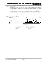
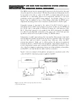
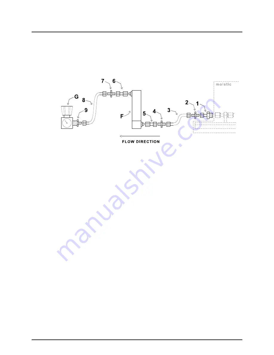
Figures 1 and 2 show the system positioned so that the gas inlet is on the right side and the flow direction is to the left.
The standard arrangement is for the back pressure regulator (if it is needed) to sit freely on the bench. A regulator panel mounting
nut and gauge mounting U-clamp and bezel are supplied in the AFMETCAL Configuration Kit in case you wish to mount these
components on the bench or into a bracket. If you do mount them, keep in mind that the tubing length leading to the regulator
should be minimized to reduce flow and pressure instability.
It is helpful to have a moveable vice or similar device to hold the DUT in the proper orientation during calibration.
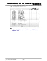
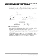
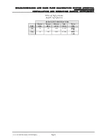
1. VCR Tube Adaptor
6. AN4 to Swage Adaptor
2. Swage Male Union
7. Swage Male Union
3. 6 in. (15 cm) PFA Tube
8. 20 in. (50 cm) PFA Tube
4. Swage Male Union
9. 4 NPT M to Swage Adaptor
5. AN4 to Swage Adaptor
Figure 2.
AFMETCAL Kit Downstream of molstic
Figure 2 shows the general setup for the portion of the system downstream of the molstic. Since DUT fittings, shapes and pressure
requirements will vary, the exact setup will also vary. Figure 2 includes each of the fittings that are supplied in the AFMETCAL
Configuration Kit. A description of which fittings can be omitted for each application is outlined below.
The lengths of the PFA tubes (3, 8) are chosen to accommodate likely positions of DUT ports and the height difference between the
bench surface and molbloc platform. For some DUTs the tubes may be selected differently than shown in Figure 2. Since enough
fittings are supplied in the AFMETCAL Configuration Kit to assemble two complete flow channel setups, duplicate tubes can be
used to provide different lengths.
Whenever possible, tubing lengths between flow components (molbloc, DUT, back pressure regulator) should be minimized,
especially for lower flows. For example, if the DUT outlet port is not elevated like the one on the rotameter in Figure 1 and Figure 2,
then a shorter tube can be substituted for the 20 in. tube (8). Also, in some cases, the DUT’s size and weight may allow it to be
supported directly by adaptors downstream of the molstic and the 6 in. tube (3) can be omitted as described below.

