background image

M O L B L O C / M O L B O X ™   L O W   M A S S   F L O W   C A L I B R A T I O N   S Y S T E M   A F M E T C A L  
C O N F I G U R A T I O N S    
I N S T A L L A T I O N   A N D   O P E R A T I O N   M A N U A L   S U P P L E M E N T  


 Page 

©2000-2008 

DH Instruments, a Fluke Company


m o l s t i c s  

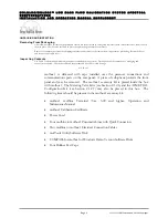
molstics are packaged in long corrugated boxes surrounded by protective foam.  
Accessory kits are packaged with the molstics and include Viton O-rings, 
and installation instructions.  Low flow molstic accessory kits also include a filler rod 
which can be inserted in the VCR close coupling fitting at the molbloc’s outlet.  
The filler is used to reduce dead volume between the molbloc and DUT to help 
stabilize pressure when measuring very low flows (see molstic installation 
instruction sheet).  In systems where there is already significant volume from tubing, 
the rod will not have much effect. 

Both low and mid flow molstics are delivered with cradles to fit small 
molblocs installed.  The cradles on the single mid flow molstic need to be replaced 
with the large molbloc cradles to fit the larger 30 slm (3E4) molbloc.  All of the 
molstic parts downstream of the cradles also need to be moved further downstream 
to accommodate the 30 slm (3E4) molbloc’s greater length.  The molstic base has 
pre-drilled holes for each standard bracket and cradle in both positions (see the molstic 
installation instructions). 

M E T E R I N G   V A L V E   K I T S  

Metering valve kits are made up of several items including the metering valve, a valve 
bracket and panel mounting nut, a coupling bracket and grommet, a VCR close 
coupling union, two Viton O-rings and Allen screws.  Each item in the kit is 
packaged in a plastic bag.  These kits are to be mounted on the downstream end of 
each molstic channel. 

Four low flow metering valve kits and one mid/high flow metering valve kit are 
delivered.  Mount the low flow metering valve kits on the dual low flow and dual mid 
flow molstics.  Mount the mid/hi flow metering valve kit on the single mid flow 
molstic.  The manufacturer’s part number written on each metering valve’s body 
differentiates the low flow valves from the mid/high flow valve.  The low flow valve 
is SS-

4BMG

-VCR.  The mid/high flow valve is SS-

4BMRG

-VCR.  See Section 

2.1.2.6 for specific mounting instructions for the metering valve kits. 


  Never forcefully tighten the molstic metering valves.  They are not designed for positive shut-off, only flow 

control. 


Содержание MOLBLOC

Страница 1: ... 2000 2008 DH Instruments a Fluke Company molbloc molbox Low Mass Flow Calibration System AFMETCAL Configurations Installation and Operation Manual Supplement ...

Страница 2: ...ectronic or mechanical for any purpose without the express written permission of DH Instruments a Fluke Company 4765 East Beautiful Lane Phoenix AZ 85044 5318 USA DH Instruments makes sincere efforts to ensure accuracy and quality of its published materials however no warranty expressed or implied is provided DH Instruments disclaims any responsibility or liability for any direct or indirect damag...

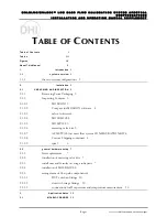
Страница 3: ...Packaging 3 2 1 2 Inspecting Contents 3 2 1 2 1 MOLBOX1 3 2 1 2 2 Compass for MOLBOX software 4 2 1 2 3 caltool software 4 2 1 2 4 MOLBLOCS4 2 1 2 5 MOLSTICS 5 2 1 2 6 metering valve kits 5 2 1 2 7 AFMETCAL low mass flow system CONFIGURATION KIT 6 2 1 2 8 Custom Shipping containers 6 2 1 2 9 rpm3 6 2 2 general hardware setup 7 2 2 1 Site requirements 7 2 2 2 installation of metering valve kits 7 2...

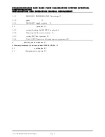
Страница 4: ...ny Page ii 3 1 1 MOLBLOC PRESSURE AND Flow ranges 13 3 1 2 gases 15 3 1 3 MOLBLOC supply pressure 15 3 2 operation 16 3 2 1 setting checking the MOLSTIC regulator16 3 2 2 Preparing for flow measurements 16 3 2 3 setting DUT back pressure 19 3 2 4 Entry of DUT pressure and temperature measurements20 4 Warranty and Recalibration 21 4 1Warranty statement for deliveries under f33660 99 f7000 21 4 2 re...

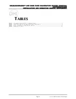
Страница 5: ... D O P E R A T I O N M A N U A L S U P P L E M E N T Page iii 2000 2008 DH Instruments a Fluke Company T TA AB BL LE ES S Table 1 Components List for AFMETCAL Configuration Systems 2 Table 2 Parts List for AFMETCAL Configuration Mass Flow Kit P N 401578 6 Table 3 molbloc Usable Ranges with High Pressure Calibration 13 Table 4 Warranty Service Centers 22 ...

Страница 6: ... O P E R A T I O N M A N U A L S U P P L E M E N T Page iv 2000 2008 DH Instruments a Fluke Company F FI IG GU UR RE ES S Figure 1 Arrangement of Flow Path Components 8 Figure 2 AFMETCAL Kit Downstream of molstic 9 Figure 3 Connection of RPM3 and Temperature Measurement Device for DUT with Back Pressure 11 Figure 4 AFMETCAL Configuration molbloc Label 13 ...

Страница 7: ... 01 466 2062 It is intended to be used as a supplement to the molbox1 molbloc Terminal Ver 5 00 and higher Operation and Maintenance Manual RPM3 Operation and Maintenance Manual and COMPASS for molbox User s Manual Version 4 00 The molbox1 molblocs and COMPASS for molbox software provided in AFMETCAL system configurations are standard products identical to the commercial versions covered in the st...

Страница 8: ...A S S F L O W C A L I B R A T I O N S Y S T E M A F M E T C A L C O N F I G U R A T I O N S I N S T A L L A T I O N A N D O P E R A T I O N M A N U A L S U P P L E M E N T 2000 2008 DH Instruments a Fluke Company Page vi N NO OT TE ES S ...

Страница 9: ...The other is the calibration exchange system Their differences are summarized below in Section 1 1 1 Table 1 lists the specific components included in each configuration the two system configurations BASIC AFMETCAL CONFIGURATION The basic configuration includes a molbox molstics and five molblocs to handle flows up to 40 slm COMPASS for molbox software metering valve kits and the AFMETCAL Configur...

Страница 10: ...5 5E3 slm molbloc 1 1 3069524 401042 30 3E4 slm molbloc 1 1 3069773 401318 Dual Low Flow molstic 1 1 3069712 401244 Single Mid Flow molstic 1 1 3069764 401317 Dual Mid molstic 1 1 3069786 401319 Low Flow Metering Valve Kit 4 4 3069799 401320 Mid high Flow Metering Valve Kit 1 1 3350751 401578 AF Config Mass Flow Kit 1 1 FAM0003 RPM3 A0100b Pressure Monitor 1 1 2758335 100847 RS232 Cable 1 1 306966...

Страница 11: ...included in your system Descriptions of the components packaging and accessories are below Check that all items are present and have NO visible damage m o l b o x 1 molbox1 is delivered with caps installed over the pressure connections and communications ports on the rear panel A piece of cellophane protects the front panel and may be removed The molbox1 accessory kit is placed inside the box with...

Страница 12: ...covers The cases are shipped inside cardboard boxes holding two molblocs each There is a recessed square on the front of the hard cases on which to apply the molbloc s calibration sticker if you desire Calibration stickers are delivered with each calibration certificate molbloc end fittings pneumatic pressure quick connectors and communication ports are capped for protection and cleanliness Each m...

Страница 13: ...lstic parts downstream of the cradles also need to be moved further downstream to accommodate the 30 slm 3E4 molbloc s greater length The molstic base has pre drilled holes for each standard bracket and cradle in both positions see the molstic installation instructions M E T E R I N G V A L V E K I T S Metering valve kits are made up of several items including the metering valve a valve bracket an...

Страница 14: ...02664 AN4 F to Swage Adaptor 2 3372514 102824 Back Pressure Regulator 2 3137757 102727 Regulator Panel Mounting Nut 2 3372506 102823 Back Pressure Gauge 2 3232378 101450 Z 20 in 50 cm PFA Tube 1 4 in OD 2 3232378 101450 Z 6 in 15 cm PFA Tube 1 4 in OD 1 3375667 550110 Manual AFMETCAL Configurations 1 3372523 102849 VCR Plug 1 2758335 100847 RS232 Cable C U S T O M S H I P P I N G C O N T A I N E R...

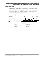
Страница 15: ...o be configured for the large 30 slm 3E4 molbloc prior to installing the metering valve The metering valve is inserted into its bracket leaving the panel mounting nut loose The metering valve bracket is attached to the downstream end of the molstic by fastening the Allen screws into pre drilled holes on the molstic An arrow on the metering valve body indicates the proper flow direction The male VC...

Страница 16: ...t Install the molblocs with the arrow on the silver sticker pointing in the direction of the flow Be sure to use the Viton O rings provided when connecting the molbloc VCR end fittings see molstic instruction sheet When using molstics with metering valve kits installed it is easiest to install molblocs by connecting the downstream fitting first then inserting the upstream O ring and connecting the...

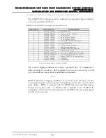
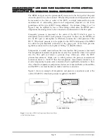
Страница 17: ...to Swage Adaptor Figure 2 AFMETCAL Kit Downstream of molstic Figure 2 shows the general setup for the portion of the system downstream of the molstic Since DUT fittings shapes and pressure requirements will vary the exact setup will also vary Figure 2 includes each of the fittings that are supplied in the AFMETCAL Configuration Kit A description of which fittings can be omitted for each applicatio...

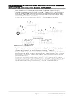
Страница 18: ...omitted C O N N E C T I O N S F O R D U T P R E S S U R E A N D T E M P E R A T U R E M E A S U R E M E N T Some kinds of DUTs require that flow corrections are made based on the density of the gas flowing through the DUT during calibration The density correction is made from knowledge of the pressure and temperature of the gas as measured near the DUT The measurements of pressure and temperature ...

Страница 19: ... measure the outlet pressure of the DUT When back pressure is to be applied to the DUT and measured the RPM3 can either be pneumatically connected to the gauge port of the back pressure regulator or connected to a tee in place of fitting 7 as described above Temperature is usually measured near the same location that pressure is measured The temperature measurement probe may create a flow restrict...

Страница 20: ...A S S F L O W C A L I B R A T I O N S Y S T E M A F M E T C A L C O N F I G U R A T I O N S I N S T A L L A T I O N A N D O P E R A T I O N M A N U A L S U P P L E M E N T 2000 2008 DH Instruments a Fluke Company Page 12 N NO OT TE ES S ...

Страница 21: ... 1 000 sccm 1 slm For most range designations the usable range of the molbloc is double the nominal range as in the previous example An exception is the 30 slm 3E4 molbloc which becomes a 40 slm range when given a high pressure calibration molblocs are calibrated over their entire usable range usable flow range calibrated flow range The maximum flow and minimum flow at which molblocs can be most a...

Страница 22: ... S T A L L A T I O N A N D O P E R A T I O N M A N U A L S U P P L E M E N T 2000 2008 DH Instruments a Fluke Company Page 14 full mod high pressure single P high pressure RANGE SIZE DESIGNATIONS GAS 10 sccm 1E1 50 sccm 5E1 500 sccm 5E2 5 slm 5E3 30 slm 3E4 N2 20 100 1 000 10 000 40 000 7 500 Air 20 100 1 000 10 000 40 000 7 200 ...

Страница 23: ...and the molbloc usable ranges listed in Table 3 are not valid for gases for which molblocs have not been calibrated MOLBLOC supply pressure molblocs with high pressure calibrations should always be used with an inlet pressure of 76 psia 525 kPaa AFMETCAL configuration molblocs are actually calibrated to operate with a range of inlet pressures from 47 to 76 psia 325 to 525 kPaa but since the molblo...

Страница 24: ...low flow molstic install the 500 sccm 5E2 molbloc with higher range molblocs the pressure stabilizes more quickly Using the molstic metering valve set a flow near the lowest flow point that will be measured using that molstic If using a low flow molstic set a flow of at least 10 sccm Allow the flow to stabilize Viewing the molbloc inlet upstream pressure using molbox1 press P T on the molbox1 see ...

Страница 25: ...onnectors with check valves so the last gas used will remain in the lines when they are disconnected Tare This procedure zeros the molbox1 differential pressure measurement The tare should always be performed with the normal operating pressure supplied to the molbloc The DUT does not need to be connected to perform the tare Open the molstic shut off valve allowing the gas supply to reach the molbl...

Страница 26: ...tream of the DUT before running the system leak check However DUTs that are normally operated at lower pressures will usually fail the pressurized leak check even they do not leak at their normal operating pressures DUTs may also be damaged by the elevated pressure if they are designed for low pressure use In general the components included in the closed system during a system leak check should no...

Страница 27: ...ingle COMPASS test a test option may be selected to run a molbox purge and or system leak check after each molbloc change in addition to the beginning of the test setting DUT back pressure Once the system is setup and the procedures described in Section 3 2 2 have been performed the user can begin setting flows establishing steady state stable flow conditions and taking data If the DUT is to be ca...

Страница 28: ...t System Set the Pressure Measurement selection to RPM3 Ex and click OK If the Pressure Measurement selection is left as Manual then the user will be prompted to enter visually collected pressure data during tests In the COMPASS Setup menu select Hardware and go to the Pressure tab Double click RPM3 Ex in the list to display the Edit Pressure Measuring Device window Select the correct RS232 port I...

Страница 29: ...HI and any of its Authorized Service Providers obligations with respect to this warranty are limited to the repair or replacement of defective products after their inspection and verification of such defects All products to be considered for repair or replacement are to be returned to DHI or its Authorized Service Provider after receiving authorization from DHI or its Authorized Service Provider T...

Страница 30: ...H INSTRUMENTS A FLUKE COMPANY AUTHORIZED SERVICE PROVIDERS 2008 JAN COMPANY ADDRESS TELEPHONE FAX EMAIL NORMAL SUPPORT REGION DH Instruments a Fluke Company 4765 East Beautiful Lane Phoenix AZ 85044 5318 USA Tel 602 431 9100 Fax 602 431 9559 cal repair dhinstruments com Worldwide Minerva Meettechniek B V Chrysantstraat 1 3812 WX Amersfoort the NETHERLANDS Tel 31 33 46 22 000 Fax 31 33 46 22 218 in...

Отзывы: