background image

8-Port Dual Output

Fiber Tap

FTAP-SX50-2X8

FTAP-SX62-2X8

FTAP-LX-2X8

HARDWARE GUIDE

PN 2530069

September 2005

© 2005 Fluke Networks, Inc.  All rights reserved.  Printed in USA.

All product names are trademarks of their respective companies.

Содержание FTAP-LX-2X8

Страница 1: ...put Fiber Tap FTAP SX50 2X8 FTAP SX62 2X8 FTAP LX 2X8 HARDWARE GUIDE PN 2530069 September 2005 2005 Fluke Networks Inc All rights reserved Printed in USA All product names are trademarks of their respective companies ...

Страница 2: ...nce to radio communications Operation of this equipment in a residential area is likely to cause harmful interference in which case the user will be required to correct the interference at one s own expense C CE ER RT TI IF FI IC CA AT TI IO ON NS S This equipment has been tested and found to meet the radiated and conducted emission limits for a Class B product of EN 55022 to the EMC Directive 89 ...

Страница 3: ...ge repair or replacement of a defective product which is returned to a Fluke Networks authorized service center within the warranty period To obtain warranty service contact your Technical Assistance Center Support information can be found in the System Recovery section at the end of this manual Fluke Networks assumes no risk for damage in transit Following warranty repair the product will be retu...

Страница 4: ...vels 9 PANEL DESCRIPTION 10 Front panel 10 Rear panel 10 11 SWITCH REMOVAL REPLACEMENT 12 FTAP x 2X8 section removal 12 13 Switch section replacement 13 DAISY CHAIN ADDRESSING 14 Connection instructions 14 15 Hardware installation 16 17 TROUBLESHOOTING 18 CARE AND MAINTENANCE 19 Avoiding rough handling 19 Cleaning carefully 19 Providing adequate ventilation 19 Safety information 19 Service and adj...

Страница 5: ... a central location using Fluke Networks MANAgents software for Windows 9x NT 2000 XP following the procedure outline in the MANAgents software guide AUDIENCE This hardware guide is written for the person who must install and connect a FTAP x 2X8 Fiber Tap The installer is assumed to be familiar with Windows9x NT 2000 XP knows how networks operate and has operating knowledge of network appliances ...

Страница 6: ...he FTAP x 2X8 Fiber Tap affords the ultimate in network integrity The unique design allows for effortless topology upgrades and enables the active components to be swapped without breaking network links It provides permanent bypass whether access is taking place or not to meet whatever monitoring or analysis requirements you may have and it allows the sharing of network tools between fiber segment...

Страница 7: ...ate of the analysis system the input power to the FTAP x 2X8 Fiber Tap from both the transmit and receive side of each segment must be within the power level ranges recommended in the Specifications section of this hardware guide By optimizing the performance of the analyzer path it will be able to detect and resolve network errors Figure 1 FTAP x 2X8 connectivity diagram IMPORTANT Some documents ...

Страница 8: ...tored above below or hang behind the switch Remove the DB9 male lead labeled B tie wrap to make the entire lead length available for installation Connect the DRL460 6 6 control Y cable DB9 male lead labeled B to the COM 1 port of the other appliance NOTE The FTAP x 2X8 Fiber Tap uses a DRL470 6 6 6 6 control quad cable to connect to the DB9 COM 1 port of each network appliance 4 Connect network fi...

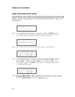
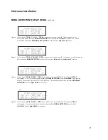
Страница 9: ...splayed Figure 3 Next the Fluke Networks logo will illuminate the display indicating successful initialization Figure 4 The scrolling graphic displays the FTAP x 2X8 Fiber Tap model number FTAP SX50 2X8 FTAP SX62 2X8 or FTAP LX 2X8 depending on your configuration and switch status TAP A OFFLINE _ _ and TAP B OFFLINE _ _ TAP A and TAP B are OFFLINE and all optical signals are ignored The two horizo...

Страница 10: ...m both the network left port 5 and right port 5 receivers Figure 8 Switch status TAP B DAISY TAP B is connected to the next FTAP x 2X8 Fiber Tap in a DAISY configuration The first horizontal bar indicates SIGNAL DETECTION from the left DAISY port receiver which is connected to the next FTAP x 2X8 Fiber Tap The second horizontal bar indicates NO SIGNAL DETECTION from the right DAISY port receiver F...

Страница 11: ...ltage and current output ratings is 5V DC at 9 0A This power supply is provided with Safety Extra Low Voltage SELV circuits which separate hazardous voltages with a grounded system on the primary input The power supply has been certified by UL CUL and TUV and is CE approved PERFORMANCE 8 Specifications FEATURE SPECIFICATION NOMINAL POWER REQUIREMENTS 100 240V AC at 50 60Hz 5V DC at 9 0A Safety Ext...

Страница 12: ...r path the analyzer will be able to perform as it was designed to detect and resolve network errors NOTE Dynamic Range dBm measurements include 4dB shift for spitter and connectors also 1dB shift for output power for connectors on top row LX Longwave 1270 to 1355 nm single mode SX Shortwave 770 to 860 nm multi mode 9 Specifications FIBER TAP MODEL OPTICAL LEVEL BIT RATE DYNAMIC RANGE dBm 1X10 12 B...

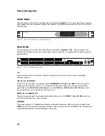
Страница 13: ...the network providing network integrity TAP A1 A2 B1 AND B2 These SC connector ports are cabled to the NIC MONITOR card Port 1 and Port 2 Rx SC connectors respectively of network analyzers The FTAP x 2X8 Fiber Tap connects the selected network fiber port 1 8 to the TAP A1 A2 or B1 B2 port but two TAPS i e TAP A1 A2 or B1 B2 port cannot be connected to the same channel at the same time DAISY A1 A2 ...

Страница 14: ...tor USB style and is cabled to the CONTROL port of the next Fiber Tap when daisy chained POWER POWER is supplied through a miniature 4 pin female quick lock circular connector used to connect to either the provided 100 240V AC 50 60Hz supply or external 5V DC power supply 11 Panel Description ...

Страница 15: ...network links providing permanent bypass Typical removal is described as follows Figure 12 FTAP x 2X8 rear panel thumbscrew locations IMPORTANT A warning symbol in the unit indicates that the fluorescent display module relies on a high voltage 70V DC source Display module capacitors store energy and require more than one minute of discharge time to avoid personal injury or equipment damage Handle ...

Страница 16: ...de from the TAP and DAISY ports of the Fiber Tap 4 Loosen the two rear panel thumbscrews as shown in Figure 12 about 5 turns in a counter clockwise direction until they spring free from the main chassis section threads Apply gentle but equal pressure to the thumbscrews to start the forward motion of the Fiber Tap section and remove it from the rack enclosure as shown in Figure 13 SWITCH SECTION RE...

Страница 17: ...t inches from the tap connector so it can be easily stored behind the Fluke Networks switch Figure 14 Connectivity diagram for individual daisy chain addressing 2 Connect the miniature 4 pin male quick lock power supply connector into the POWER port of the Fiber Tap and plug the power supply into the external power source wall receptacle The model number and switch status will scroll on the displa...

Страница 18: ...K port connected to the CONTROL port of the next FTAP x 2X8 Fiber Tap using a DRL448 6 cable 3 Connect a miniature 4 pin male quick lock power supply connector into the POWER port of each FTAP x 2X8 Fiber Tap and then plug each power supply into the external power source wall receptacle The message Loading OS Version x xx will illuminate indicating power is on The Fiber Tap model number and switch...

Страница 19: ... SC to SC multi mode fiber cables 3 Connect the DAISY A1 A2 B1 and B2 ports of the first switch respectively to the TAP A1 A2 B1 and B2 ports of the second switch using DRL408 2m SC to SC multi mode fiber cables Any subsequent daisy chained switches respectively have their DAISY A1 A2 B1 and B2 ports connected to the TAP A1 A2 B1 and B2 ports of the next switch using DRL408 2m multi mode fiber cab...

Страница 20: ...ctivity diagram Daisy Chain Addressing 17 Transport to Console DRL460 6 6 Control Y Cable A B Transport to Console DRL448 6 Control Cable DRL448 6 Control Cable DRL448 6 Control Cable Fiber Cable Fiber Cable Fiber Cable Fiber Cable Network Appliance A Network Appliance B ...

Страница 21: ...nd still no response is detected then substitute with another DRL460 6 6 DRL448 6 cable ideally one known to operate correctly UNABLE TO SELECT SEGMENT PORT 1 Confirm that the fiber cable connects the TAP port of the FTAP x 2X8 Fiber Tap to the MONITOR port of the network appliance 2 If you are unable to capture data or access one segment swap out the cable with another Fluke Networks cable ideall...

Страница 22: ... requirements WARNINGS If this product is used in a manner not specified by the manufacturer the protections provided by the product may be impaired Do not use the tap if it is damaged Before using inspect the case Look for cracked or missing case parts Pay particular attention to the insulation surrounding the connectors Do not operate the tap around explosive gas vapor or dust When servicing the...

Страница 23: ...st Fluke Networks distributor or service center call Australia 61 2 8850 3333 or 61 3 9329 0244 Beijing 86 10 6512 3435 Brazil 11 3044 1277 Canada 1 800 363 5853 Europe 44 1923 281 300 Hong Kong 852 2721 3228 Japan 81 3 3434 0181 Korea 82 2 539 6311 Singapore 65 6738 5655 Taiwan 886 2 227 83199 USA 1 800 283 5853 Anywhere in the world 1 425 446 4519 Visit our website for the latest list of phone n...

Отзывы: