background image


DURCO MARK 3 ISO FRAME MOUNTED  ENGLISH  85392719  06-12 


Page 10 of 52 

flowserve.com


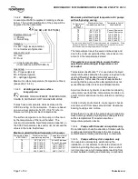
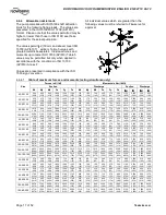
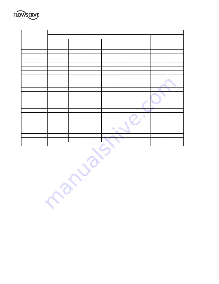
Motor size 
and speed 

kW (hp) 

Typical sound pressure level L

pA

 at 1 m reference 20 

µ

Pa, dBA 

3 550 r/min 

2 900 r/min 

1 750 r/min 

1 450 r/min 

Pump 

only 

Pump 

and 

motor 

Pump 

only 

Pump 

and  

motor 

Pump 

only 

Pump 

and  

motor 

Pump 

only 

Pump 

and  

motor 

<0.55 (<0.75) 

72 

72 

64 

65 

62 

64 

62 

64 

0.75 (1) 

72 

72 

64 

66 

62 

64 

62 

64 

1.1 (1.5) 

74 

74 

66 

67 

64 

64 

62 

63 

1.5 (2) 

74 

74 

66 

71 

64 

64 

62 

63 

2.2 (3) 

75 

76 

68 

72 

65 

66 

63 

64 

3 (4) 

75 

76 

70 

73 

65 

66 

63 

64 

4 (5) 

75 

76 

71 

73 

65 

66 

63 

64 

5.5 (7.5) 

76 

77 

72 

75 

66 

67 

64 

65 

7.5 (10) 

76 

77 

72 

75 

66 

67 

64 

65 

11(15) 

80 

81 

76 

78 

70 

71 

68 

69 

15 (20) 

80 

81 

76 

78 

70 

71 

68 

69 

18.5 (25) 

81 

81 

77 

78 

71 

71 

69 

71 

22 (30) 

81 

81 

77 

79 

71 

71 

69 

71 

30 (40) 

83 

83 

79 

81 

73 

73 

71 

73 

37 (50) 

83 

83 

79 

81 

73 

73 

71 

73 

45 (60) 

86 

86 

82 

84 

76 

76 

74 

76 

55 (75) 

86 

86 

82 

84 

76 

76 

74 

76 

75 (100) 

87 

87 

83 

85 

77 

77 

75 

77 

90 (120) 

87 

88 

83 

85 

77 

78 

75 

78 

110 (150) 

89 

90 

85 

87 

79 

80 

77 

80 

150 (200) 

89 

90 

85 

87 

79 

80 

77 

80 

200 (270) 

1


1


1


1


85


87 

83


85 

300 (400) 

– 

87


90 

85


86 

1

  The noise level of machines in this range will most likely be of values which require noise exposure control, but typical values are inappropriate. 

Note:  for 1 180 and 960 r/min reduce 1 450 r/min values by 2 dBA.  For 880 and 720 r/min reduce 1 450 r/min values by 3 dBA. 
 

Содержание Durco Mark 3

Страница 1: ...on Maintenance Standard two piece bearing frame foot mounted centreline mounted and unitized self priming chemical process pumps PCN 85392719 06 12 E Original instructions These instructions must be read prior to installing operating using and maintaining this equipment ...

Страница 2: ...IONING START UP OPERATION AND SHUTDOWN 20 5 1 Pre commissioning procedure 21 5 2 Pump lubricants 22 5 3 Impeller clearance 23 5 4 Direction of rotation 23 5 5 Guarding 23 5 6 Priming and auxiliary supplies 23 5 7 Starting the pump 23 5 8 Running the pump 24 5 9 Stopping and shutdown 25 5 10 Hydraulic mechanical and electrical duty 25 Page 6 MAINTENANCE 26 6 1 General 26 6 2 Maintenance schedule 26...

Страница 3: ...nance 6 26 Maintenance schedule 6 2 27 Name nomenclature 3 2 12 Nameplate 1 7 1 9 Nozzle loads 4 6 4 17 Operating limits 3 4 1 13 Ordering spare parts 6 3 1 28 Part assemblies 4 2 13 Parts interchangeability 8 4 45 Parts lists 8 39 Performance 3 4 13 Piping 4 6 15 Pre commissioning 5 1 21 Priming and auxiliary supplies 5 6 23 Page Protection systems 4 9 20 Reassembly 6 10 Assembly 32 Receipt and u...

Страница 4: ...e Atmospheres ATEX Where applicable the Directives and any additional Approvals cover important safety aspects relating to machinery and equipment and the satisfactory provision of technical documents and safety instructions Where applicable this document incorporates information relevant to these Directives and Approvals To confirm the Approvals applying and if the product is CE marked check the ...

Страница 5: ...training and instruction must be provided If required the operator may commission the manufacturer supplier to provide applicable training Always coordinate repair activity with operations and health and safety personnel and follow all plant safety requirements and applicable safety and health laws and regulations 1 6 3 Safety action This is a summary of conditions and actions to help prevent inju...

Страница 6: ...eal DO NOT RUN THE PUMP AT ABNORMALLY HIGH OR LOW FLOW RATES Operating at a flow rate higher than normal or at a flow rate with no back pressure on the pump may overload the motor and cause cavitation Low flow rates may cause a reduction in pump bearing life overheating of the pump instability and cavitation vibration 1 6 4 Products used in potentially explosive atmospheres Measures are required t...

Страница 7: ...0 C 392 F 300 C 572 F 450 C 842 F Consult Flowserve Consult Flowserve 110 C 230 F 175 C 347 F 270 C 518 F 350 C 662 F The table only takes the ATEX temperature class into consideration Pump design or material as well as component design or material may further limit the maximum working temperature of the liquid The temperature rise at the seals and bearings and due to the minimum permitted flow ra...

Страница 8: ...ure cloth is damp For ATEX the coupling must be selected to comply with 94 9 EC Correct coupling alignment must be maintained Additional requirement for metallic 1 6 4 9 pumps on non metallic baseplates When metallic components are fitted on a non metallic baseplate they must be individually earthed Preventing leakage 1 6 4 10 The pump must only be used to handle liquids for which it has been appr...

Страница 9: ...n attention is drawn to the following table to give an indication of equipment noise level so that you can take the appropriate action in your plant Pump noise level is dependent on a number of operational factors flow rate pipework design and acoustic characteristics of the building and so the values given are subject to a 3 dBA tolerance and cannot be guaranteed Similarly the motor noise assumed...

Страница 10: ... 76 77 72 75 66 67 64 65 7 5 10 76 77 72 75 66 67 64 65 11 15 80 81 76 78 70 71 68 69 15 20 80 81 76 78 70 71 68 69 18 5 25 81 81 77 78 71 71 69 71 22 30 81 81 77 79 71 71 69 71 30 40 83 83 79 81 73 73 71 73 37 50 83 83 79 81 73 73 71 73 45 60 86 86 82 84 76 76 74 76 55 75 86 86 82 84 76 76 74 76 75 100 87 87 83 85 77 77 75 77 90 120 87 88 83 85 77 78 75 78 110 150 89 90 85 87 79 80 77 80 150 200 ...

Страница 11: ...nts in excess of 25 kg 55 lb Fully trained personnel must carry out lifting in accordance with local regulations Slings ropes and other lifting gear should be positioned where they cannot slip and where a balanced lift is obtained The angle between sling or ropes used for lifting must not exceed 60 2 3 1 Bare pump The bare pump should be lifted as shown 2 3 2 Pump and folded steel or polycrete bas...

Страница 12: ...f priming casing R Recessed impeller low shear design N Center line mounted high pressure casing H High pressure casing 200 Nominal impeller diameter A Extended flow hydraulic B standard hydraulic RV Impeller design RV Reverse vane OP Open The typical nomenclature above is the general guide to the Durco Mark3 ISO configuration description Identify the actual pump size and serial number from the pu...

Страница 13: ...aximum ambient temperature 40 ºC 104 ºF Normal minimum ambient temperature 20 ºC 4 ºF Maximum pump speed refer to the nameplate 4 INSTALLATION Equipment operated in hazardous locations must comply with the relevant explosion protection regulations See section 1 6 4 Products used in potentially explosive atmospheres 4 1 Location The pump should be located to allow room for access ventilation mainte...

Страница 14: ...d during transportation or handling If necessary align the motor to the pump not the pump to the motor Alignment is achieved by adding or removing shims under the motor feet and also moving the motor horizontally as required In some cases where the alignment cannot be achieved it will be necessary to move the pump before recommencing the above procedure For couplings with narrow flanges use a dial...

Страница 15: ... fitted may be partly opened during the priming cycle to freely vent the air 2 An automatic air release valve may be fitted to the discharge pipework between the pump and any valves providing that gases and vapors given off are environmentally safe and acceptable for release into the atmosphere 3 An air bleed pipe may be run from the discharge pipework between the pump and any valves back to the s...

Страница 16: ...ure drop across the screen can be measured When the unit is being started the gauges on each side of the screen should be carefully watched An increase in the differential pressure between the two gauges indicates that the screen is becoming clogged with dirt and scale At this point the pump should be shut down and the screen cleaned and or replaced A spool piece should be installed in suction lin...

Страница 17: ... 640 470 1 800 400 1 500 340 1 200 270 190 140 180 130 190 140 460 100 370 80 580 130 1 150 850 2 630 590 320 240 830 190 50 32 160 930 690 460 340 700 520 1 800 400 1 500 340 1 200 270 290 210 210 150 220 160 500 110 400 90 590 130 1 250 920 2 630 590 420 310 870 200 65 40 160 1 640 1 210 820 600 1 230 910 2 300 520 1 840 410 1 500 340 560 410 280 210 420 310 860 190 700 160 1 070 240 2 210 1 630...

Страница 18: ... 970 1 340 990 2 000 1 480 3 570 800 2 850 640 2 320 520 1 640 1 210 820 600 1 230 910 1 840 410 1 490 330 2 300 520 3 600 2 660 5 120 1 150 2 210 1 630 3 300 740 125 80 315 4 710 3 470 1 740 1 280 3 540 2 610 4 650 1 050 5 020 1 130 3 020 680 2 670 1 970 990 730 2 000 1 480 2 110 470 2 320 520 3 570 800 6 140 4 530 7 480 1 680 3 480 2 570 4 750 1 070 125 100 315 4 710 3 470 1 740 1 280 3 540 2 61...

Страница 19: ... between the seals compatible with the pumped liquid With back to back double seals the barrier liquid should be at a minimum pressure of 1 bar 14 5 psi above the maximum pressure on the pump side of the inner seal see appropriate chart The barrier liquid pressure must not exceed limitations of the seal on the atmospheric side For toxic service the barrier liquid supply and discharge must be handl...

Страница 20: ...rate wiring diagram See section 5 4 Direction of rotation before connecting the motor to the electrical supply 4 8 Final shaft alignment check After connecting piping to the pump rotate the shaft several times by hand to ensure there is no binding and all parts are free Recheck the coupling alignment as previously described to ensure no pipe strain If pipe strain exists correct piping 4 9 Protecti...

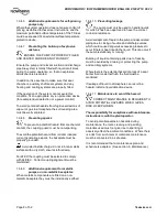
Страница 21: ...nally vent balanced Where an adjustable body Denco oiler is fitted this should be set to the height shown in the following diagram The oil filled bottle should then be refitted so as to return it to the upright position Filling should be repeated until oil remains visible within the bottle Approximate oil volumes are shown in section 5 2 2 Bearing sizes and capacities Grease lubricated pumps and e...

Страница 22: ...ash bath lubrication to avoid changing to Viton seals in the bearing housing It is available in the EU from Renox S N C Via Bologna 12 60019 Senigallia ANOCONA Italy 5 2 2 Bearing sizes and capacities Frame size Grease lubricated medium duty bearings Grease lubricated heavy duty bearings Grease lubricated bearing capacities g oz Pump end Drive end Pump end Drive end Pump end Drive end 1 2 3 4 6207...

Страница 23: ...guards must remain captive in the guard to comply with the Machinery Directive 2006 42 EC When releasing such guards the fasteners must be unscrewed in an appropriate way to ensure that the fasteners remain captive Whenever guarding is removed or disturbed ensure that all the protective guards are securely refitted prior to start up 5 6 Priming and auxiliary supplies 5 6 1 Filling and priming non ...

Страница 24: ...pump with the outlet valve closed for a period longer than 30 seconds l If the pump has to fill the system it may take a short time before the outlet is pressurized m If NO pressure or LOW pressure STOP the pump Refer to section 7 Faults causes and remedies for fault diagnosis 5 8 Running the pump 5 8 1 Pumps fitted with packed gland If the pump has a packed gland there must be some leakage from t...

Страница 25: ...ity unfiltered Vertical configurations mm s in sec r m s Normal N 7 1 0 28 Alarm N x 1 25 9 0 0 35 Shutdown trip N x 2 0 14 2 0 56 5 8 5 Stop start frequency Pump sets are normally suitable for the number of equally spaced stop starts per hour shown in the table below Check capability of the driver and control starting system before commissioning Motor rating kW hp Maximum stop starts per hour Up ...

Страница 26: ... by authorized and qualified personnel who have adequately familiarized themselves with the subject matter by studying this manual in detail See also section 1 6 2 Any work on the machine must be performed when it is at a standstill It is imperative that the procedure for shutting down the machine is followed as described in section 5 9 On completion of work all guards and safety devices must be r...

Страница 27: ...ceptable limits d Check the level and condition of oil lubricant On grease lubricated pumps check running hours since last recharge of grease or complete grease change e Check any auxiliary supplies eg heating cooling if fitted are functioning correctly Refer to the manuals of any associated equipment for routine checks needed 6 2 2 Periodic inspection six monthly a Check foundation bolts for secu...

Страница 28: ...ange to the original design specification modification or use of a non standard part will invalidate the pump safety certification 6 3 2 Storage of spares Spares should be stored in a clean dry area away from vibration Inspection and re treatment of metallic surfaces if necessary with preservative is recommended at 6 monthly intervals 6 4 Recommended spares For two years operation as per VDMA 2429...

Страница 29: ...eller setting of 0 4 mm 0 016 in simply move the bearing carrier 3240 counterclockwise four indicator patterns for the required clearance c Use the indicator pattern closest to the top centre of the bearing housing as the reference point to begin adjustment Temp ºC ºF Clearance mm in Impellers up to 210 mm Impellers 211 mm to 260 mm Impellers over 260 mm except 150 400 200 400 150 500 50 122 100 2...

Страница 30: ... 1 mm 0 004 in Example for an impeller setting of 1 5 mm 0 059 in simply move the bearing carrier clockwise fifteen indicator patterns for the required clearance d Use the indicator pattern closest to the top centre of the bearing housing as the reference point to begin adjustment e After obtaining the proper clearance of 1 5 mm 0 059 in to 2 mm 0 079 in tighten the set screws 6570 1 2 evenly to l...

Страница 31: ...eal gland away c Remove the two cover nuts 6580 d Loosen the grub screws used in most mechanical seals e Carefully pull off the cover and mechanical seal rotating element s f Remove the seal cover g Remove shaft sleeve if fitted h On non cartridge seals the stationary seat remains in the cover mechanical seal gland with its sealing member Remove only if damaged or worn out i On pumps fitted with g...

Страница 32: ...ection If the pair of angular contact thrust bearings are to be fitted these must be mounted back to back as shown below Grease retainer 3864 Grease retainer clearance type is only fitted on grease lubricated units The following methods are recommended for fitting the bearings onto the shaft Method 1 Use a hotplate hot bath oven or induction heater to heat the bearing race so it can easily be plac...

Страница 33: ...t into the cover 1220 or mechanical seal cover 4213 ensuring that the seating ring is not deformed Where an anti rotation pin is fitted ensure that correct engagement with the slot is achieved d Place any separate seal covers over the shaft 2100 e Refer to manufacturer s instructions to position the mechanical seal rotating elements Tighten any drive screws in the seal drive collar For precise com...

Страница 34: ...essary See section 6 7 Setting impeller clearance e Ensure that all other items have been re attached and all fasteners tightened to the correct torques then follow the instructions in the sections on Installation and Commissioning 6 11 Sealing arrangements The following section shows details of the seal arrangements The dimensions provided are for non step balanced mechanical seals conforming to ...

Страница 35: ...4 0 173 18 3 0 720 4 3 0 169 315 10 6 0 417 4 4 0 173 18 3 0 720 4 3 0 169 4 7 0 185 32 3 1 272 400 27 0 1 063 4 3 0 169 3 5 0 138 24 0 0 945 500 10 6 0 417 4 4 0 173 18 3 0 720 4 3 0 169 4 7 0 185 32 3 1 272 6 11 2 Cartridge seal types Cartridge seal in Seal Sentry conical 6 11 2 1 cover Hooked sleeve cartridge seal 6 11 2 2 For S see seal supplier s instructions 6 11 3 Tandem seal types Tandem s...

Страница 36: ... 1 Frame 2 Frame 3 Frame 4 125 11 0 0 433 160 11 0 0 433 17 5 0 689 200 6 0 0 236 17 5 0 689 250 12 4 0 488 14 4 0 567 315 12 4 0 488 14 3 0 563 32 3 1 272 400 5 7 0 224 24 0 0 945 500 12 4 0 488 14 3 0 563 32 3 1 272 6 11 5 External seal types External seal 6 11 5 1 D drain 6 11 6 Packed gland seal types Packed gland with fibre packing 6 11 6 1 4120 4130 4134 F Rp in flush BI Rp in barrier liquid...

Страница 37: ... suction pipe is airtight Air leaks into pump through mechanical seal sleeve joints casing joint or pipe lugs Check and replace faulty parts CONSULT FLOWSERVE Foot valve too small Investigate replacing the foot valve Foot valve partially clogged Clean foot valve Inlet of suction pipe insufficiently submerged Check out system design Speed too low CONSULT FLOWSERVE Speed too high CONSULT FLOWSERVE T...

Страница 38: ...check bearings for excessive wear Impeller out of balance resulting in vibration Check and CONSULT FLOWSERVE Abrasive solids in liquid pumped Internal misalignment of parts preventing seal ring and seat from mating properly Mechanical seal was run dry Check mechanical seal condition and source of dry running and repair Internal misalignment due to improper repairs causing impeller to rub Check met...

Страница 39: ...0 Bearing housing 3240 Bearing carrier 3712 1 Bearing locknut 3712 2 Bearing locknut 3853 1 Grease nipples grease lubrication only 3853 2 Grease nipples grease lubrication only 3855 Constant level oiler 3856 Oil sight gauge 4200 Mechanical seal 4305 Shaft seal ring 4330 Labyrinth ring 4590 1 Gasket 4590 2 Gasket 4610 1 O ring 4610 2 O ring 6544 Circlip 6569 1 Plug filler 6569 2 Plug 6569 3 Plug ma...

Страница 40: ...sing 3240 Bearing carrier 3712 1 Bearing locknut 3712 2 Bearing locknut 3853 1 Grease nipples grease lubrication only 3853 2 Grease nipples grease lubrication only 3855 Constant level oiler 3856 Oil sight gauge 4200 Mechanical seal 4305 Shaft seal ring 4330 Labyrinth ring 4590 1 Gasket 4590 2 Gasket 4610 1 O ring 4610 2 O ring 6544 Circlip 6569 1 Plug filler 6569 2 Plug 6569 3 Plug magnetic 6570 1...

Страница 41: ...134 Support foot 3200 Bearing housing 3240 Bearing carrier 3712 1 Bearing locknut 3712 2 Bearing locknut 3853 1 Grease nipples grease lubrication only 3853 2 Grease nipples grease lubrication only 3855 Constant level oiler 3856 Oil sight gauge 4200 Mechanical seal 4305 Shaft seal ring 4330 Labyrinth ring 4590 Gasket 4610 1 O ring 4610 2 O ring 6544 Circlip 6569 1 Plug filler 6569 2 Plug magnetic 6...

Страница 42: ...housing 3240 Bearing carrier 3712 1 Bearing locknut 3712 2 Bearing locknut 3853 1 Grease nipples grease lubrication only 3853 2 Grease nipples grease lubrication only 3855 Constant level oiler oil lubrication only 3856 Oil sight gauge 4200 Mechanical seal 4305 Shaft seal ring 4330 Labyrinth ring 4590 1 Gasket 4590 2 Gasket 4610 1 O ring 4610 2 O ring 6544 Circlip 6569 1 Plug filler 6569 2 Plug 656...

Страница 43: ...g 3240 Bearing carrier 3712 1 Bearing locknut 3712 2 Bearing locknut 3853 1 Grease nipples grease lubrication only 3853 2 Grease nipples grease lubrication only 3855 Constant level oiler 3856 Oil sight gauge 4200 Mechanical seal 4305 Shaft seal ring 4330 Labyrinth ring 4590 1 Gasket 4590 2 Gasket 4610 1 O ring 4610 2 O ring 6544 Circlip 6569 1 Plug filler 6569 2 Plug 6569 3 Plug magnetic 6569 4 Pl...

Страница 44: ... impeller option Key drive design for 304 316 stainless steel and above secure screw with PTFE sealant Loctite 577 Item Description 2100 Shaft 2200 Impeller 2400 Sleeve if fitted 2912 1 Impeller nut 2912 2 Impeller nut 4590 4 Gasket 4610 4 O ring if sleeve fitted 4610 5 O ring 6570 6 Screw 6700 2 Key 2100 2400 6700 2 2200 4610 5 2912 1 4590 4 6570 6 2912 2 4610 4 includes heli coil 6589 SOLID SHAF...

Страница 45: ...12 Page 45 of 52 flowserve com 8 4 Parts interchangeability 8 4 1 Durco Mark3 ISO A hydraulic parts interchangeability Drawing taken from E576 159 issue date 12 04 12 Note Pump sizes marked with a in the table above are only available with open impeller ...

Страница 46: ...H 85392719 06 12 Page 46 of 52 flowserve com 8 4 2 Durco Mark3 ISO B hydraulic parts interchangeability Drawing taken from E576 159 issue date 12 04 12 Note Pump sizes marked with a in the table above are only available with open impeller ...

Страница 47: ...DURCO MARK 3 ISO FRAME MOUNTED ENGLISH 85392719 06 12 Page 47 of 52 flowserve com 8 4 3 Self priming and recessed impeller pumps parts interchangeability Drawing taken from E576 159 issue date 12 04 12 ...

Страница 48: ...er Instructions such as for a driver instrumentation controller sub driver seals sealant system mounting component etc are included under this section If further copies of these are required they should be obtained from the purchaser for retention with these User Instructions Where any pre printed set of User Instructions are used and satisfactory quality can be maintained only by avoiding copying...

Страница 49: ...DURCO MARK 3 ISO FRAME MOUNTED ENGLISH 85392719 06 12 Page 49 of 52 flowserve com Notes ...

Страница 50: ...DURCO MARK 3 ISO FRAME MOUNTED ENGLISH 85392719 06 12 Page 50 of 52 flowserve com Notes ...

Страница 51: ...DURCO MARK 3 ISO FRAME MOUNTED ENGLISH 85392719 06 12 Page 51 of 52 flowserve com Notes ...

Страница 52: ...7 57 Repair Service Fax 33 2 43 40 58 17 To find your local Flowserve representative please use the Sales Support Locator System found at www flowserve com FLOWSERVE REGIONAL SALES OFFICES USA and Canada Flowserve Corporation 5215 North O Connor Blvd Suite 2300 Irving Texas 75039 5421 USA Telephone 1 972 443 6500 Fax 1 972 443 6800 Europe Middle East Africa Flowserve FSG Italy Worthing S r l Via R...

Отзывы: