


26
2.9
Fault Finding
Pulse meters have two distinct sections: the mechanical wetted section housing the rotors
and the electrical section housing the pulse output board. Meters fitted with integral
instruments have these two sections plus the instrument. The aim of fault finding is to trace
the source of the fault to one of these sections. If a fault is traced to an instrument section,
refer to the relevant instruction manual.
Below are basic fault finding steps.
Step 1
-
Check application, installation and set up;
refer to installation sections for
installation and application factors that may affect the meter operation including incorrect
wiring. Check meter specifications for incorrect flow rate, temperature, pressure, or
materials compatibility.
Step 2 - Check for blockages;
The most common cause of fault/unsatisfactory meter
operation, particularly for new or altered installations, is due to blockage within the system
or meter caused by foreign particles such as weld slag, sealing tape or compound, rust, etc.
Step 3 - Ensure flow is present;
No flow or lower than normal minimum flow may be
attributed to a blocked strainer, jammed or damaged rotors within the flowmeter, a
malfunctioning pump, closed valves or low liquid level in feeder tank.
Step 4 - Ensure oval gears within meter are rotating;
Rotation of the oval gears can be
heard by holding a screw driver blade to the meter body and pressing the handle hard
against the ear lobe. If necessary test the meter with the flow turned off and turned on to
familiarize yourself with the audible rotation signature.
Step 5 - Ensure pulses are being generated during flowing condition;
a multi-meter is often
not fast enough to distinguish the pulse train from the reed switch or Hall Effect sensor. An
oscilloscope will allow you to view the output pulse train. When viewing the Hall effect
sensor signal ensure a pull up resistor is installed between the pulse output and the supply
voltage (refer electrical installation).
Step 6 - Confirm Instrument Operation;
if an associated instrument is connected to the
flowmeter confirm its operation by simulating a pulse input onto the flow input terminals.
In most instances, a contact closure on the flow input terminals is an adequate simulation.
Содержание Oval Gear
Страница 1: ...Industrial Oval Gear Flowmeters with pulse output or electronic display Operation Manual ...
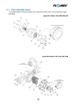
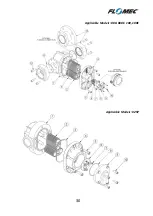
Страница 30: ...30 Applicable Models 080 080E 100 100E Applicable Models 025P ...
Страница 34: ...34 Notes ...
Страница 35: ...35 Notes ...


