background image

[

7.2.5 — Power supply (optional)

]

ThermaCAM™ PM575/595 

Operator’s Manual

48

7.2.5

Power supply (optional)

CE certified.
UL and CSA approved.

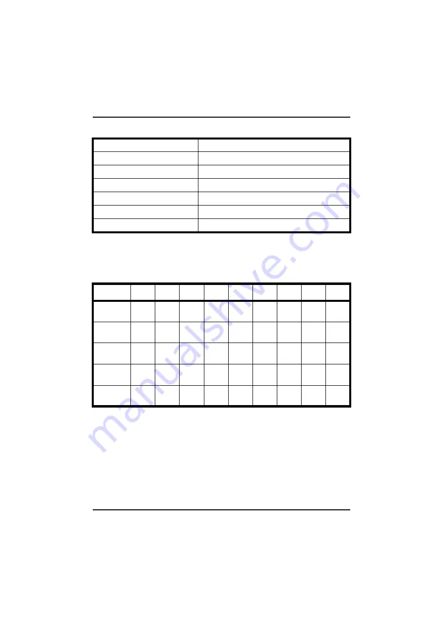
7.3

Lens data

* At close focus.

Input:

100–240 VAC, 1.3 A.

Frequency:

50/60 Hz.

Output:

13.5 VDC.

Weight:

0.7 kg (1.55 lbs)

Maximum output:

55 W

Size:

200 x 96 x 60 mm (7.87" 3.78" 2.36")

Cable length:

1.2 m (4 ft)

OBJECT 
DISTANCE

0.3

0.5

2.0

3.0

5.0

10.0

30.0

100.0

(M)


HOR FOV
IFOV

-
-

-
-

-
-

-
-

0.5
1.7

1.2
3.6

3.6
11.3

12.2
38.0

(M)
(mm)

12°
HOR FOV
IFOV

-
-

-
-

0.4*
1.3

0.6
2.0

1.1
3.5

2.1
6.6

6.3
20.0

21.0
66.0

(M)
(mm)

24°
HOR FOV
IFOV

-
-

0.2*
0.7

0.8
2.6

1.3
4.0

2.1
6.6

4.2
13.0

12.0
40.0

42.0
130.0

(M)
(mm)

45°
HOR FOV
IFOV

0.2*
0.8

0.4
1.3

1.7
5.3

2.5
7.8

4.2
13.0

8.3
26.0

25.0
78.0

83.0
260.0

(M)
(mm)

80°
HOR FOV
IFOV

0.6
1.8

0.9
2.9

3.4
10.8

5.1
16.0

8.5
26.5

16.9
52.3

50.4
158.0

169.0
524.0

(M)
(mm)

Содержание ThermaCAM PM575

Страница 1: ...ThermaCAM PM575 595 Operator s Manual ...

Страница 2: ... Sweden Tel 46 0 8 753 27 50 Fax 46 0 8 755 07 52 France Tel 33 0 1 41 33 97 97 Fax 33 0 1 47 36 18 32 Germany Tel 49 0 6995 0090 0 Fax 49 0 6995 0090 40 Italy Tel 39 0 2 3909121 Fax 39 0 2 39005185 UK Tel 44 0 1732 220011 Fax 44 0 1732 220014 ...

Страница 3: ...ThermaCAM PM575 595 FLIR Systems AB May 1999 Publ No 557 369 Ed A Operator s Manual ...

Страница 4: ......

Страница 5: ...es 9 4 1 2 PC card 9 4 1 3 Battery 9 4 1 4 Shoulder strap 9 4 1 5 Headset 10 4 2 First time operation 10 4 2 1 To get an image 10 4 2 2 To set a new language 10 4 2 3 To measure a temperature 11 4 2 4 To save an image 11 4 2 5 To add a voice comment to an image 11 4 2 6 To add text comments to an image 11 4 2 7 To recall a stored image and listen to a voice comment 12 4 2 8 To recall a previously ...

Страница 6: ...nu 24 5 5 1 1 Open 24 5 5 1 2 Save 25 5 5 1 3 Periodic save 26 5 5 1 4 Voice comment 26 5 5 1 4 1Voice comment info panel 27 5 5 1 5 Text comment 27 5 5 1 6 Delete image 28 5 5 1 7 Directory 29 5 5 1 8 Report comment 29 5 5 1 8 1Report comment info panel 29 5 5 2 Analysis menu 30 5 5 2 1 Obj par 30 5 5 2 2 Ref temp 31 5 5 2 3 Spot 31 5 5 2 4 Area 32 5 5 2 5 Profile 32 5 5 2 6 Isotherm 33 5 5 3 Ima...

Страница 7: ...38 5 5 4 2 5 Data field 38 5 5 4 2 6 Data background 38 5 5 4 2 7 Text comments 38 5 5 4 2 8 Scale 39 5 5 4 3 Local adapt 39 5 5 4 4 Save options 39 5 5 4 4 1 Image storage 39 5 5 4 4 2 Prompt comment 40 5 5 4 4 3 Image naming 40 5 5 4 4 4 Image file type 40 5 5 4 4 5 BMP file content 40 5 5 4 5 Date Time 40 5 5 4 6 System Info 40 6 Battery system 42 6 1 Battery 42 6 2 Battery charging 43 6 3 Usef...

Страница 8: ... object 50 8 2 1 1 Using a thermocouple 50 8 2 1 2 Using reference emissivity 50 8 3 Ambient temperature 50 8 4 Distance 50 8 5 Relative humidity 50 9 Theory of thermography 51 9 1 Introduction 51 9 2 The electromagnetic spectrum 51 9 3 Blackbody radiation 52 9 3 1 Planck s law 52 9 3 2 Wien s displacement law 54 9 3 3 The Stefan Boltzmann law 55 9 3 4 Non blackbody emitters 55 9 4 Infrared semi t...

Страница 9: ...ct to FLIR or this warranty will not apply FLIR will at its option repair or replace any such defective product free of charge if upon inspection it proves to be defective in material or workmanship and pro vided that it is returned to FLIR within the said one year period FLIR has no other obligation or liability for defects than those set forth above No other warranty is expressed or implied FLIR...

Страница 10: ...nd manufactured has been certified in accordance with the standard for ISO 9001 FLIR Systems AB is committed to a policy of continuous development therefore we reserve the right to make changes and improvements on any of the products described in this manual without prior notice All functions described in this manual are not available in both camera models ...

Страница 11: ...y placed on the camera allowing fingertip control of major functions A built in menu system also gives easy access to an advanced simple to use cam era software for increased functionality To document the object under inspection it is possible to capture and store images onto a removable PC card It is also possible to store together with every image voice comments and or text comments including in...

Страница 12: ... in a transport case The sys tem comprises ThermaCAM PM575 595 camera with a built in 24 lens PC card Batteries 2 Fast charger with cable Shoulder strap Video cable Lens cap Operator s Manual Calibration protocol Transport case Headset Optional accessories Power supply with cable 7 lens 12 lens 45 lens 80 lens Extension cable 5 m 16 4 ft ...

Страница 13: ...king and assembly FLIR Systems AB Publ No 557 369 Ed A 5 PC software AGEMA Report High temperature options Remote control handle Camera handle Figure 2 2 How to pack the ThermaCAM PM575 595 in the transport case ...

Страница 14: ...ol You accept the menu choice and quit the menu mode by pressing the button The button also means Accept or Confirm Press the A auto button 2 to get the best image in the viewfinder automatically When this button is pressed an automatic calibration is also performed Press the S save button 3 shortly to switch between a frozen image and a live image To store the image to the PC card press the S but...

Страница 15: ...er 7 can be adjusted by turning the adjustment ring either clockwise or counter clockwise For further information on the direct access buttons see User interface on page 14 3 2 Connections There are three connectors on the camera 12 VDC connector For connection to the power cable from battery belt or power supply This connector also provides S VHS signals or on some camera models 14 bit digital si...

Страница 16: ... 3 2 Connections ThermaCAM PM575 595 Operator s Manual 8 Figure 3 2 Camera connectors ...

Страница 17: ...g the release button on the back of the camera downwards Insert the disk with the connector side i e the bottom side of the disk to the right and the connectors facing the camera 2 To remove the PC card open the hatch and press the eject button After the PC card has been inserted the camera software will check that it hasn t got any errors This will be indicated in the viewfinder by the words Chec...

Страница 18: ...he battery into the battery compartment on the back of the camera 2 Remove the lens cover from the camera 3 Press the green on off button to start the camera After approx 15 seconds an image with the FLIR logotype will appear and will be displayed until the camera controls are ready for use 4 Adjust the viewfinder focus to obtain the best display focus for your eyes 5 Point the camera at a warm ob...

Страница 19: ...he Analysis menu again 4 2 4 To save an image 1 Press the A button and focus the image 2 Press the S button to freeze the image 3 To save hold down the S button for one second or until the filename e g E123232 of the image appears Press the S button briefly to go to live mode 4 2 5 To add a voice comment to an image 1 Connect the headset to the headset connector and place it on your head See also ...

Страница 20: ...ontrol bar for open ing files will now appear at the bottom of the screen 3 To choose the image you would like to open move the joystick up and down If the image is in another directory go to the directory selection box by moving the joystick to the right When the desired image file name appears press to select the image 4 To listen to the voice message go to the Voice comment function in the File...

Страница 21: ... box Setup Im age Text comments None 4 Select Text comment in the File menu when the image is shown A dialog box will appear and the current text comments are displayed at the bottom of the screen above the data fields If Text comments Value only or Text comments Value and label is presently selected in the Setup Image dialog box Setup Image 5 The current text comments are displayed at the bottom ...

Страница 22: ...means continue confirm or exit Pressing in normal mode will bring up the menu system and put the camera in menu mode Pressing in menu mode Activates the selected function or command in the menus Confirms and leaves the selected choices Auto adjust button 2 Press the button marked A to set the best image The camera will automatically adjust the viewed temperature span and level and will also adjust...

Страница 23: ...s the menu system putting the cam era in normal mode In normal focus zoom mode it activates a special feature N B While the C button is held down the level and span can be adjusted with the joystick Joystick left right Decreases increases span Joystick down up Decreases increases level Joystick 5 The joystick can be moved in four directions left right up and down Functionality in menu mode Change ...

Страница 24: ...me time They are only meant to show the operator the different types of menu objects Figure 5 2 Menu objects example 1 1 Menu area with pull down menus 2 Spot meter crosshair 3 Pull down menu 4 Critical info e g Battery is empty 5 Joystick control 6 Data presentation one to three lines one to five if the text comments option is enabled Figure 5 3 Menu objects example 2 explanations overleaf ...

Страница 25: ...g Frozen or Saving 2 Dialog box e g Setup Analysis 3 Control box Figure 5 4 Menu objects example 3 1 Result table i e measurement presentation area 2 Profile 3 Area Figure 5 5 Menu objects example 4 1 Confirm box 2 Temperature scale 3 Selection box e g Del image or Change dir ...

Страница 26: ...be executed and the menu area will be removed Pressing the C button will remove the pull down menu area and restore the normal function for the joystick i e focus zoom 5 3 1 Control box Some selections in the menu area result in showing a control box in the bottom left hand corner of the screen Figure 5 6 Control box The control box is a horizontal table with different selection possibilities The ...

Страница 27: ... vertical dialog box Up down Change item value alternative The selected item is marked white dark grey Pressing the button results in a function dependent action see Menu functions on page 6 Pressing the C button will normally remove the dialog box cancel the changes and put the camera in normal mode i e focus zoom function for the joystick 5 3 3 Confirm boxes Some selections pressing or C result ...

Страница 28: ...ivated the temperature difference between two defined measurement functions is displayed If the reference temperature is acti vated Analysis Ref temp it is displayed in the bottom line of the result table If one or two functions are selected each of these functions values are dis played in the result table The value is calculated as the difference between the function s temperature and the referen...

Страница 29: ...hen a PC card ATA disk is inserted Frozen Msg is displayed when the image is frozen Saving G0101 01 Msg is displayed during the time an image with the name G0101 01 is written to the disk Adjusting Msg is displayed when the camera performs an auto adjustment G0101 01 The recalled image name and the speaker symbol are displayed if the image contains a voice comment G0101 01 T The recalled image nam...

Страница 30: ...rd Msg is displayed if a non ATA disk is inserted in the camera The message will be displayed until the disk is removed Disk error Msg is displayed if some kind of error is detected while reading writing to the PC card disk 5 4 File System The ThermaCAM PM575 595 uses the standard PC card ATA hard flash disks with DOS file system to record 14 bit images IMG and or BMP with voice comments and or te...

Страница 31: ...nn File directory index If index 01 99 nn nn if directory name If index 100 999 nnn The current date is 10 01 96 January 10th 1996 Two images have already been stored on this date The next image to be stored is allocated the prefix G0110 03 G digit 6 in 1996 converted to a letter 0110 January 10th 03 File index i e this is the third image generated on January 10th 1996 No extension is used for dir...

Страница 32: ...ion the camera will display the critical info Bad file format when recalling the file 5 5 Menu Functions The menu system is organised into four main groups File Analysis Image and Setup This section describes all menu functions in detail 5 5 1 File menu The file menu contains all the functions dealing with the digital image and storage of voice and or text comments i e Open Save Periodic save Voic...

Страница 33: ...igure 5 12 Confirmation panel Image exist Create new or Overwrite If Create new is selected the image on the screen will be stored in a new file with a new automatically allocated name on the disk If Overwrite is selected this will overwrite the recalled image file on the disk The same function as choosing Save in the File menu can be activated by press ing the S button for more than one second If...

Страница 34: ...about one image per second Pressing will start the recording Pressing or C will stop the recording Images will be stored as a sequence on the selected directory image no 1 under the name SEQ001 image no 2 under SEQ002 and so on If the recording is stopped and then started again the new images will be added at the end of the previous sequence on the same directory 5 5 1 4 Voice comment When pressin...

Страница 35: ... or in the root directory If the file is placed in the root directory this function will be enabled inde pendent of the selected working inspection directory The camera displays the first 15 character in each line A maximum of 9 lines is displayed The first line is selected as the heading How to use 1 Prepare an inspection by creating an inspection directory on the PC card Edit a parameter label l...

Страница 36: ...options If BMP only is selected no text comments can be made If the option Label value or Value is chosen in the Setup Image Text com ments menu the text comments appear above the data presentation field at the bottom of the screen The suffix T is also added to the saved image to indicate that a text comment is attached to the file 5 5 1 6 Delete image This function is used to delete previously sa...

Страница 37: ...d to store a general report comment within an inspection direc tory The comment will be stored in a separate file under the present inspection directory The handling is similar to the Voice comment function see Voice com ment on page 26 5 5 1 8 1 Report comment info panel The Report comment function will display a user defined ASCII text file on the screen and is enabled by selecting Report commen...

Страница 38: ...By pressing the C button when the joystick text is dis played e g Joystick Spot pos C Remove the measurement function will be dis abled In order to move or resize a function s measuring point on the screen e g a crosshair or area the operator has to confirm this function by highlighting it in the Analysis menu The measuring point can then be moved with the joystick 5 5 2 1 Obj par This function is...

Страница 39: ...erature can be set to any one of the active mea surement functions by higlighting that particular function and then selecting Ref temp It is also possible to set the Ref temp manually See Obj par on page 30 N B To enable the Ref temp function see Setup menu on page 35 Example Point the Area function with Maximum option enabled Setup Analysis Area function Maximum at a good phase of a power breaker...

Страница 40: ...y the movement of the joystick in the following way while the text Joystick Area size C Remove is shown at the bottom of the screen To change the size of the area next time it is necessary to confirm Area in the Analysis menu again Joystick Up Increases the rectangle height or circle radius Joystick Down Decreases the rectangle height or circle radius Joystick Left Decreases the rectangle width or...

Страница 41: ...lt table and can be changed by moving the joystick up down while the text Joystick Isotemp C Remove is shown The isotherm width is changed by moving the joystick button left right When the required isotherm temperature has been set press the but ton to resume the normal function of the joystick i e focus zoom N B The choice Dual above below gives two Iso values in the result table 5 5 3 Image menu...

Страница 42: ...nge The camera supports two different temperature ranges If a high temperature option is installed the user will get an extra range 5 5 3 2 Freeze The function switches the frozen live status of the image It has the same effect as pressing the S button 5 5 3 3 Auto adjust The camera automatically optimises the parameter s Level Level span or Auto palette see Man adjust on page 33 for best image co...

Страница 43: ...ems are selected i e Spot Area type Area function Profile Isotherm type Isotherm width Isotherm colour Difference temp and Multiple spots By moving the joystick left right the item parameters will be changed When the button is pressed the parameters are stored and the dia log box is removed If the clear button is pressed the dialog box is removed with out storing any changed parameters 5 5 4 1 1 S...

Страница 44: ... in two consecutive temperature ranges above a set temperature will be coloured with two different preset isotherm colours Consequently two different isotherm values will be shonw in the result table If Dual Below is chosen all pixels in two consecutive temperature ranges below a set temperature will be coloured with two different preset isotherm colours Consequently two different isotherm values ...

Страница 45: ...s and Scale By moving the joystick left right the item parameters will be changed When the button is pressed the parameters are stored and the dialog box is removed If the C button is pressed the dialog box is removed without stor ing any changed parameters 5 5 4 2 1 Auto adjust The auto adjust function uses either Level Level and span or Auto palette for adjusting the image for optimal brightness...

Страница 46: ...ntains information on filter setting optional and lenses If no filter is enabled the text Filt NOF is displayed If a high temperature filter is enabled the text Filt AP1 is displayed The lense that is currently being used is indicated as FOV 12 FOV 24 or FOV 45 e g 12 24 and 45 field of view respectively In this line the selected temperature range is also displayed i e 35 1000 C 95 1832 F or 40 35...

Страница 47: ...d the dialog box is removed If the C button is pressed the dialog box is removed without storing any changed parameters Temp unit C degrees Celsius or F degrees Fahrenheit Distance unit Meters or feet Language The different languages depend on what modules have been downloaded to the camera Date format MM DD YY DD MM YY or YY MM DD Time format HH MM SS HH MM SS PM or HH MM SS 5 5 4 4 Save options ...

Страница 48: ...If BMP only is selected all images will be saved in the bitmap for mat The operator can also select IMG BMP which saves images in both for mats If any IR analysis is to be done to an image after the recording it has to be saved as IMG only or IMG BMP 5 5 4 4 5 BMP file content If BMP only or IMG BMP is selected above the operator can choose if the saved images should contain only the infrared data...

Страница 49: ...Info FLIR Systems AB Publ No 557 369 Ed A 41 stick left right another information panel is selected There are three different pan els When the button or the clear button C is pressed the information panels are removed ...

Страница 50: ...e battery gives an operation time of about 2 hours per battery When Battery low is shown in the camera it is time to change batteries by opening the hatch of the battery compartment on the back of the camera see figure above The battery shall be inserted into the battery compartment with its convex side fac ing downwards and the recessed arrow symbol facing inwards as shown on the figure The first...

Страница 51: ...hour the yellow LED will stop blinking and the battery is now charged to 100 Blinking red The battery is faulty and cannot be charged 6 3 Useful notes on the battery system There is no risk of overcharging or damaging already charged batteries If a already charged battery is inserted into the charger the charging will start but be aborted after appr five minutes when the charger senses that the ba...

Страница 52: ...00 ºC 4 930 ºF two ranges Up to 1000 ºC 1832 ºF with high temperature option Measurement accuracy 2 Thermal sensitivity 0 1 ºC Field of view F x V See Lens data on page 48 Detector type Focal Plane Array FPA uncooled microbolometer 320 x 240 pixels Spectral range 7 5 13 µm built in atmosheric filter with cut on 7 5 µm Video output Standard VHS or S VHS Viewfinder Colour LCD TFT PC card drive One s...

Страница 53: ...de NiMH battery Operating time Typically 2 hours using one battery Environmental temperature range operation 15 50 ºC 5 122 ºF Environmental temperature range storage 40 70 ºC 40 158 ºF Enclosure Metal housing protection IP54 IEC 529 Tripod mount 1 4 20 Weight 1 9 kg 4 19 lbs excluding battery 2 3 kg 5 07 lbs including battery Size 220 x 133 x 140 mm 8 66 x 5 24 x 5 5 ...

Страница 54: ...ors Figure 7 1 Pin configuration 7 2 1 12 V socket Pin 1 RS 232 TxD output data 2 RS 232 RxD input data 3 S Video Y optional 14 bit digital output 4 S Video C optional 14 bit digital output 5 S Video ground 6 Power out 11 16 V 7 Power in 11 16 V 8 Ground power 9 Ground power 10 Power in 11 16 V ...

Страница 55: ...rophone electorate type phantom feed 5 VDC 1 mA max swing 30 mVpp 4 Microphone 5 N C 7 2 3 Video socket Pin 1 Composite video 2 N C 3 N C 4 N C 5 Power out 6 Ground 7 Ground 7 2 4 Battery charger CE certified Input 100 240 VAC 50 W Frequency 50 60 Hz Output 11 18 VDC 1 8 A Weight 0 7 kg 1 55 lbs Maximum output 36 W Size 230 x 150 x 72 mm 9 06 5 90 2 83 ...

Страница 56: ...7 3 78 2 36 Cable length 1 2 m 4 ft OBJECT DISTANCE 0 3 0 5 2 0 3 0 5 0 10 0 30 0 100 0 M 7 HOR FOV IFOV 0 5 1 7 1 2 3 6 3 6 11 3 12 2 38 0 M mm 12 HOR FOV IFOV 0 4 1 3 0 6 2 0 1 1 3 5 2 1 6 6 6 3 20 0 21 0 66 0 M mm 24 HOR FOV IFOV 0 2 0 7 0 8 2 6 1 3 4 0 2 1 6 6 4 2 13 0 12 0 40 0 42 0 130 0 M mm 45 HOR FOV IFOV 0 2 0 8 0 4 1 3 1 7 5 3 2 5 7 8 4 2 13 0 8 3 26 0 25 0 78 0 83 0 260 0 M mm 80 HOR F...

Страница 57: ...ThermaCAM PM575 595 The following object parameters must however be supplied for the camera The emissivity of the object The ambient temperature The distance between the object and the camera The relative humidity 8 2 Emissivity The most important object parameter to set correctly is the emissivity which in short is a measure of how much radiation is emitted from the object compared to that from a...

Страница 58: ...w be read The temperature of the reference object must not be too close to the ambient temperature for this to work either 8 3 Ambient temperature This parameter is used to compensate for the radiation reflected in the object and the radiation emitted from the atmosphere between the camera and the object If the emissivity is low the distance very long and the object temperature relatively close to...

Страница 59: ...um They are all governed by the same laws and the only differences are those due to differences in wavelength Figure 9 1 The electromagnetic spectrum Thermography makes use of the infrared spectral band At the short wavelength end the boundary lies at the limit of visual perception in the deep red At the long wavelength end it merges with the microwave radio wavelengths in the millimetre range The...

Страница 60: ...lackness which is obtained at the aperture is nearly equal to a blackbody and almost perfect for all wavelengths By providing such an isothermal cavity with a suitable heater it becomes what is termed a cavity radiator An isothermal cavity heated to a uniform temperature generates blackbody radiation the characteristics of which are determined solely by the temperature of the cavity Such cavity ra...

Страница 61: ... m2 µm If the factor is excluded the dimension will be Watt m2 m Planck s formula when plotted graphically for various temperatures produces a family of curves Following any particular Planck curve the spectral emittance is zero at λ 0 then increases rapidly to a maximum at a wavelength λmax and after passing it approaches zero again at very long wavelengths The higher the temper ature the shorter...

Страница 62: ...ery hot star such as Sirius 11 000 K emitting bluish white light radiates with the peak of spectral radiant emittance occurring within the invisible ultraviolet spectrum at wavelength 0 27 µm The sun approx 6 000 K emits yellow light peaking at about 0 5 µm in the mid dle of the visible light spectrum At room temperature 300 K the peak of radiant emittance lies at 9 7 µm in the far infrared while ...

Страница 63: ...ding surfaces at room temperatures which do not vary too drastically from the temperature of the body or of course the addition of clothing 9 3 4 Non blackbody emitters So far only blackbody radiators and blackbody radiation have been discussed However real objects almost never comply with these laws over an extended wavelength region although they may approach the blackbody behaviour in cer tain ...

Страница 64: ...and wavelength Expressed mathematically this can be written as the ratio of the spectral emit tance of the object to that of a blackbody as follows Generally speaking there are three types of radiation source distinguished by the ways in which the spectral emittance of each varies with wavelength A blackbody for which ε1 ε 1 A greybody for which ε1 ε constant less than 1 A selective radiator for w...

Страница 65: ... 4 Infrared semi transparent materials Consider now a non metallic semi transparent body let us say in the form of a thick flat plate of plastic material When the plate is heated radiation generated within its volume must work its way toward the surfaces through the material in which it is partially absorbed Moreover when it arrives at the surface some of it is reflected back into the interior The...

Страница 66: ...of the plate is sought When the resulting geometrical series is summed the effec tive emissivity of a semi transparent plate is obtained as This formula represents a generalisation of Kirchhoff s law which is reduced when the plate becomes opaque τλ 0 to the single formula This last relation is a particularly convenient one because it is often easier to mea sure reflectance than to measure emissiv...

Страница 67: ......

Страница 68: ......

Отзывы: