FLIR Quasar CM-6405 Скачать руководство пользователя страница 7

CM-6405 / CM-6408 Quick Install Guide  Revision 120

December 2021

This document does not contain any export-controlled information.

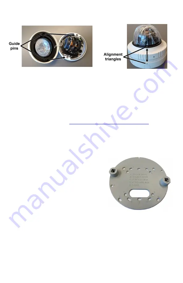
To re-attach the dome cover:

a. Using the two guide pins on the dome cover and the triangles on the cover and

on the base, carefully align and position the dome cover onto the base.

b. Securely tighten the outer ring.

c. Lock the ring. Using the Torx wrench, tighten the screw on the outer ring that

secures the cover to the base.

8 Fit Mounting Hardware

If required, install the mounting hardware for the camera according to the
instructions for the hardware.

9 Remove Cover and Separate Base

Repeat the steps described in 

4.2 Remove Cover and Separate Base

.

10 Install Mounting Bracket

You can install the mounting bracket on standard electrical boxes or directly on a
secure, flush, and vibration-free surface.

To install the mounting bracket on a standard electrical box:

Attach the bracket to the box using:

·

The holes in the mounting bracket,
according to the types of boxes engraved on
the bracket

·

The corresponding holes in the box

·

Suitable bolts, washers, and nuts (not
included in the camera kit)

To install the mounting bracket directly on
a surface:

a. Choose four widely spaced mounting holes

on the bracket for optimum flat surface mounting.

b. Using the bracket as a template to mark the surface, drill four anchor holes.

c. (Optional) If necessary, drill a hole wide enough for routing cables.

d. Hammer the four plastic screw anchors into the drilled holes.

e. Insert the anchors and then attach the bracket to the surface using the four M4

25mm self-tapping screws included in the camera kit.

When tightening the screws, the holes in the mounting plate allow for making small
adjustments to the bracket's position.

Содержание Quasar CM-6405

Страница 1: ...mera in a surrounding environment subject to extremely high temperature can result in an explosion or the leakage of flammable liquid or gas Subjecting the camera to extremely low air pressure can res...

Страница 2: ...sheet protecting the dome To remove the dome cover a Using the Torx wrench loosen the screw on the camera s outer circular ring that secures the dome cover to the camera base b While firmly holding th...

Страница 3: ...The camera itself does not have a power on off switch Do not supply power to the camera until you have completely finished connecting it Connectors Connector Connection 1 RJ 45 Two LEDs Attach a Cat...

Страница 4: ...to the pin assignment shown 2 Audio In R 7 Alarm Out 3 GND 8 Alarm In 4 Audio Out L 9 Alarm In 5 Audio Out R Warnings Do not connect an external power supply to the nine pin audio alarm I O terminal...

Страница 5: ...Teledyne FLIR s Latitude VMS or is on a network with static IP addressing you can manually specify the camera s IP address using the DNA tool or the camera s web page The camera s default IP address i...

Страница 6: ...Format b In the Change Video Format window select PAL c Click Update wait for Ok status to appear and then click Close For more information about using the DNA tool to configure one or more cameras se...

Страница 7: ...al boxes or directly on a secure flush and vibration free surface To install the mounting bracket on a standard electrical box Attach the bracket to the box using The holes in the mounting bracket acc...

Страница 8: ...he base Inside base According to the information in 4 Connect the Camera connect the camera Note Connect the camera to a 24VAC or PoE power source as the primary power source and then connect 12VDC as...

Страница 9: ...10 45 c Repeat the steps described in 4 6 Re attach Cover 13 Complete Camera Setup Specify the camera s zoom and focus and format the microSD card using the camera s web page Teledyne FLIR recommends...

Страница 10: ...Security settings select Allow software to run or install even if the signature is invalid and click OK Try installing ActiveX again After a successful ActiveX installation uncheck the checkbox and cl...

Страница 11: ...at 14 Default Video Configuration Settings The camera s default Video Configuration settings appear in the following image CM 6405 2688x1944 is the default stream1 resolution Default Video Configurati...

Страница 12: ...sions 17 Register the Product Register the product at https customer flir com For warranty information see https www flir com support center warranty security flir security product warranties 18 Conta...

Отзывы: