Installing M-Series Camera Systems
432-0003-60-12 Version 100
May 2017
12
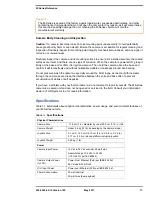
Mounting Upside Down
When the camera unit is mounted in a ball down orientation, the base
must be rotated 180 degrees relative to the bow of the vessel, so the
internal position sensors are oriented correctly. Refer to the arrow
designations on the bottom of the camera base. A camera configuration
setting accessible through the camera on-screen display (OSD) menu
system is used to configure the camera for the ball-down position. See the
M-Series Operator’s Manual
for details.
When mounting the camera in a ball down position, the installer must
ensure the camera is installed with adequate drainage so that standing
water does not collect above the cable glands. Standing water will
eventually seep past the cable gland seals and compromise the internal
electronics.
If the base of the M-Series camera must be left exposed, the exit holes
must be sealed with a Marine grade adhesive such as 3M 4200 or
equivalent. Use a sufficient amount of sealant to prevent pooling of water
above the glands.
Caution!
Installing the Joystick Control Unit (JCU)
The cable gland seal is designed for use with double-shielded category 5 Ethernet cable. To
ensure a good seal and to maintain compliance with EMI ratings, a double-shielded cable is
required.
The JCU enclosure is rated IPX6 above the JCU mounting surface/gasket.
Caution!
Standard JCU Mounting Instructions
1. Using the JCU template supplied as a guide in FLIR Doc. # 432-
0003-XX-YY, mark the location of the rectangular opening that will
allow the JCU to be recessed in the vessel’s control console. Ensure
the corners are marked precisely and cut square.
2. Apply the adhesive side of the rubber gasket to the back of the JCU
on the surface that faces the mounting platform. The JCU comes
with 4 panel mounting clamps that can be reversed when the
thickness of the panel material is less than 0.79 cm (5/16 or 0.31 in.);
see instructions below. Ensure the mounting clamps are rotated
inward and are recessed so the entire JCU fits into the hole
3. Remove boots from both ends of the Ethernet cable, as it may
interfere with the coupling gland. The boot may cause the RJ45
connector tab to depress, which can lead to intermittent connections.
4. Loosen or remove the cable gland nut on the JCU, and insert the Ethernet cable RJ45
connector through the gland nut. Once the Ethernet cable is connected to the JCU, replace the
gland nut and turn the nut 1/4 turn beyond hand tight.
Failure to properly install or seal these glands could void the camera warranty.
An installation template is provided in the ICD. If you print the template from the PDF file, ensure
that it was printed to the correct scale by checking the dimensions prior to cutting any holes.
Do not allow water
to collect above
the cable glands
Cable
gland nut
Содержание M-Series
Страница 1: ...Installation Guide M Series ...


