Installing M-Series Camera Systems
432-0003-60-12 Version 100
May 2017
11
Physical Installation
Use a thread-locking compound such as Loctite 242 or equivalent with all metal-to-metal threaded
connections.
Installing the Camera Unit
Two O-rings are provided for use during the camera installation. You should choose the one most
appropriate for your configuration:
• Part # AS568A-427 is typically used for the upright installation.
120 mm ID x 7 mm (4.75 in. ID x 0.25 in.) DIA
• Part # A3568A-334 is used for certain ball-down installations.
67 mm ID x 5 mm (2.63 in. ID x 0.19 in.) DIA
As an alternative to the mounting O-ring, you may use a marine-grade sealant such as 3M 4200 or
the equivalent.
Mounting Upright
Caution!
Using the template supplied with the camera as a guide, mark the
location of the holes for mounting the camera. Make sure the template is
oriented properly relative to the bow of the vessel; observe that the
forward direction is reversed for a ball-down installation. If the template is
printed, be sure it is printed to scale so the dimensions are correct. If you
are using the top-down installation kit, the riser itself should be used as a
template for the location of the drill holes and cable access hole.
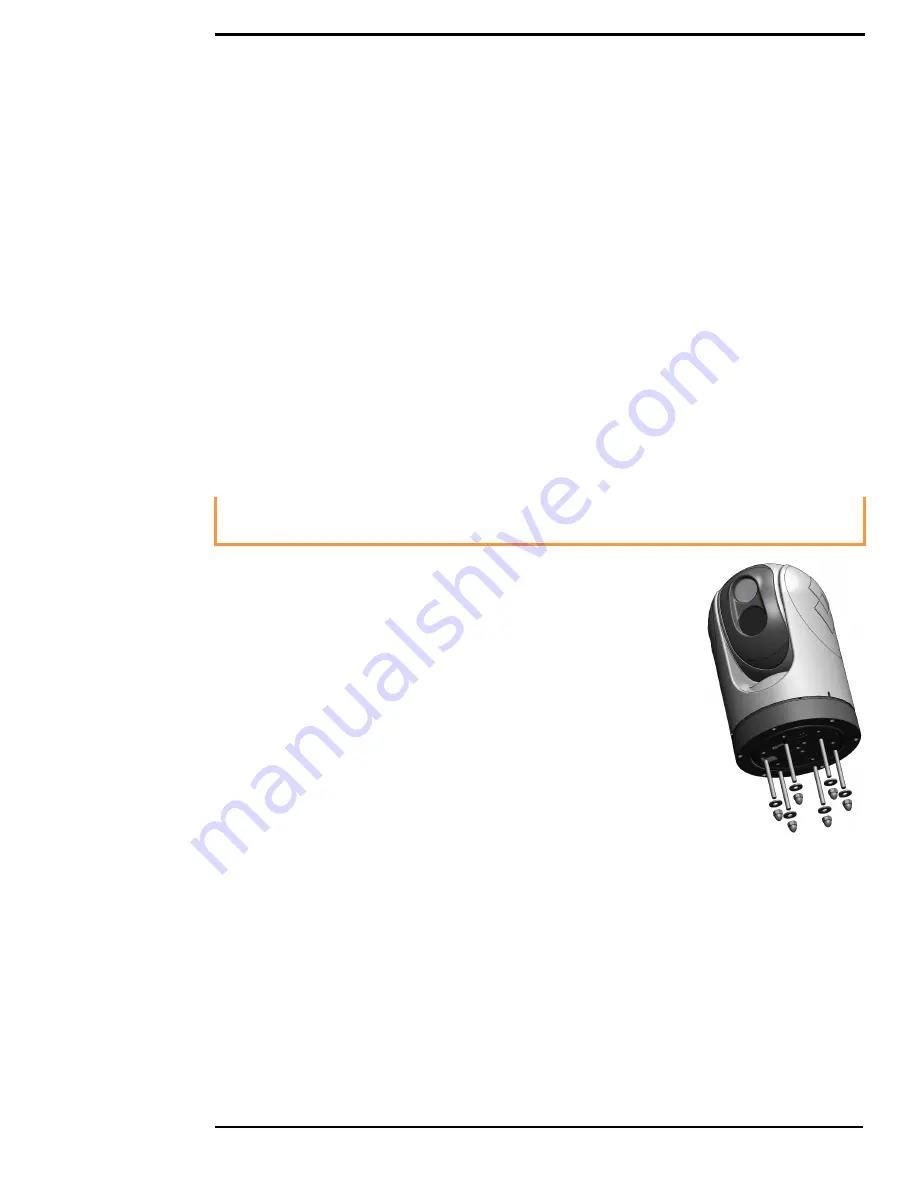
Install the six (6) threaded studs into the base of the camera with thread-
locking compound. Install the rubber O-ring in the base of the camera.
Thread the power supply, video, and Ethernet cables from the camera
through the center hole, and then place the camera on the mounting
surface so the threaded studs extend through the drilled holes. Secure
the camera body to the mounting surface with the supplied nuts and
washers. As needed, the threaded studs can be replaced with studs of a
different length or cut to a shorter length.
The cable connectors terminating the pigtail cables on the camera are not sealed connectors;
therefore, appropriate sealing steps are needed to protect the connections and the camera.
Содержание M-Series
Страница 1: ...Installation Guide M Series ...


