background image

 Configuration Menus

30

432-0003-00-10 rev 140 M-Series Operator’s Manual

Configuration Menus

In most installations, it will not be necessary to modify the factory default 
configuration settings. If the user has a set of preferred settings, it may be 
desirable to modify some of the configuration settings with the on-screen 
menu. Some settings can be saved and therefore are preserved (in the 
case of loss of power), and some settings will be configured as needed.

MENU

The MENU button is used to turn on or off the on-screen menu. When the 
on-screen menu is displayed, the joystick puck can be used to navigate 
through the menus and select various menu entries. 

To navigate the menus, use the puck to move the cursor up and down from 
one selection to the next (the puck can be moved fore and aft, or it can be 
rotated). To make a selection, press the puck (like a mouse click) or move 
the puck to the right. Once you are satisfied with your changes, press the 
MENU button to exit the menus. 

Note

The on-screen menus only appear on the thermal camera video. They 

do not appear on the video from the visible camera.

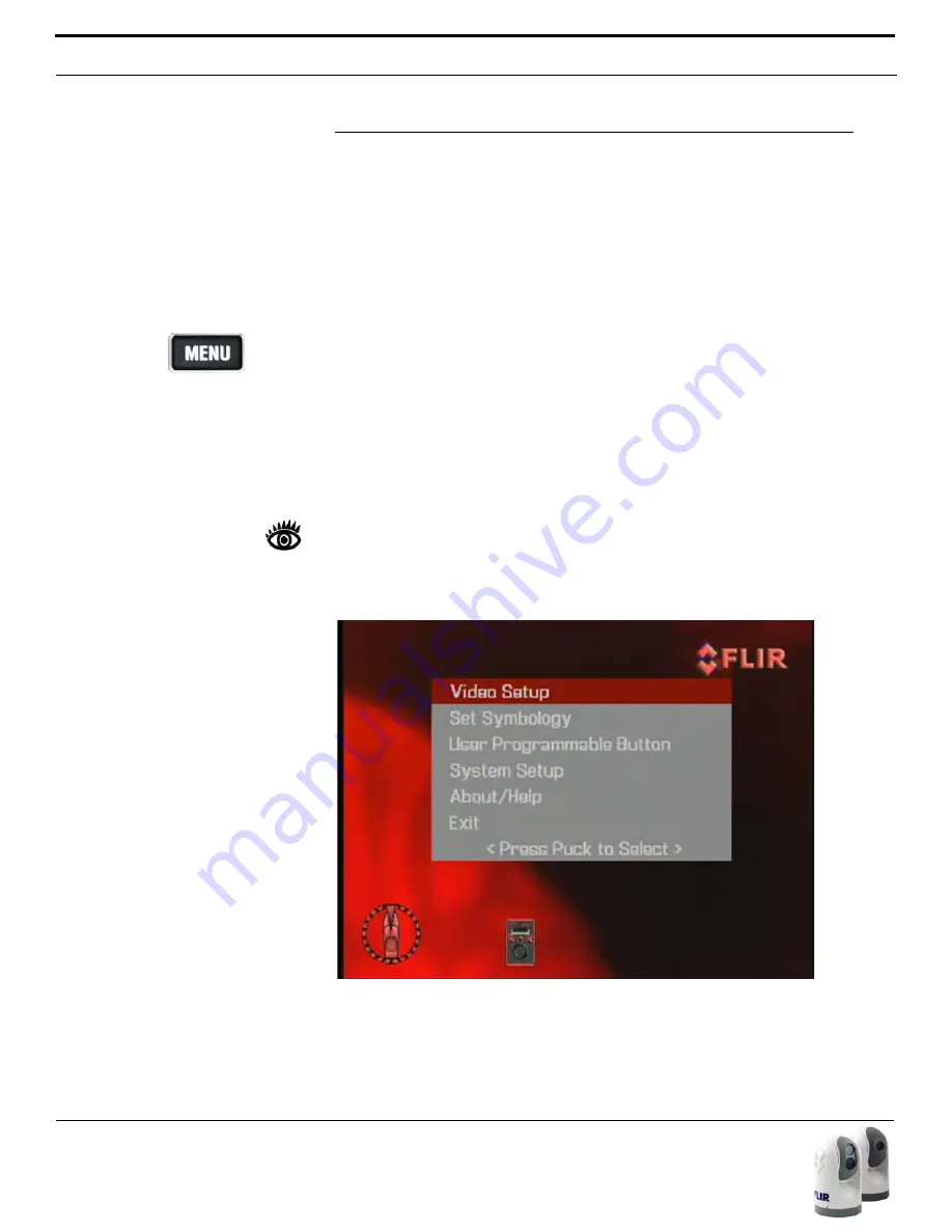
When the Menu button is pushed, the following on-screen menu is dis-
played on the thermal video:

The current menu selection is indicated by the dark red bar. 

When the MENU button is pressed 
while viewing the Visible Low-Light 
Camera, the video will switch back 
to Thermal Video to allow the 
MENU to be displayed.

Содержание M-Series

Страница 1: ...M Series 432 0003 00 10 Revision 140 January 2011 Operator s Manual ...

Страница 2: ...nd travel Please contact FLIR Systems if you have any questions FLIR Systems Inc 70 Castilian Drive Goleta CA 93117 Phone 1 888 747 FLIR 1 888 747 3547 www flir com maritime Document Number 432 0003 00 10 Version 140 Document History This document is controlled to FLIR Technology Level 1 The information contained in this document pertains to a dual use product controlled for export by the Export A...

Страница 3: ...24 Factory Default Settings 26 System Operation and Configuration 27 Operation Configuration Using JCU Buttons 28 Configuration Menus 30 Video Setup Menu 31 Set Symbology 33 User Programmable Button 34 System Setup 35 About Help 40 System Reset Functions 42 JCU Reset 42 Camera Reset 42 Operation Tips 43 Troubleshooting Tips 44 On Screen Messages 47 Restoring the Factory Network Settings 48 M Serie...

Страница 4: ...432 0003 00 10 rev 140 M Series Operator s Manual 6 Custom Network Applications 61 ...

Страница 5: ...agnetic Interference FFC Flat Field Correction FLIR Forward Looking Infrared ICD Interface Control Document IEC International Electrotechnical Commission IEEE Institute of Electrical and Electronics Engineers IR Infrared JCU Joystick Control Unit NMEA National Marine Electronics Association P T Pan Tilt PoE Power Over Ethernet SCTE Society of Cable Telecommunications Engineers SDK Software Develop...

Страница 6: ...8 432 0003 00 10 rev 140 M Series Operator s Manual ...

Страница 7: ...eries camera If you need help or have additional questions please call to speak with our support experts phone numbers listed on the back cover of this manual This manual includes information about the following topics System Description System Startup Configuration Menus Operation Tips Refer to the M Series Installation Guide FLIR Doc 432 0003 00 12 for information about how to install the camera...

Страница 8: ...ga tion system Use it in conjunction with other navigation aids and a primary manual navigation system Warning Use of insufficient wire gauge can result in fire Caution Do not open the M Series camera unit for any reason Disassem bly of the camera including removal of the cover can cause permanent damage and will void the warranty Caution Be careful not to leave fingerprints on the M Series s came...

Страница 9: ...it JCU In this manual the term camera may refer to the entire camera unit gimbal assembly or it may refer specifically to either the thermal camera or the visible camera depending on the context in which it is used The M Series gimbal and JCU are network devices and connect together with Ethernet In some installations additional cameras and JCUs will also be used and networking equipment such as P...

Страница 10: ...connected by means of a network switch If the net work switch does not have Power over Ethernet PoE capability a PoE injec tor may be used to provide power to the JCU FLIR PoE injectors are available where you purchased your M Series camera Contact FLIR 1 888 747 3547 or 33 765794194 for more informa tion regarding available accessories including JCUs PoE equipment video distribution amplifiers ca...

Страница 11: ...ther as a pair so the video can be viewed when the camera position pan or tilt is changed with the JCU The JCU can be connected to the camera directly with the supplied double shielded Ethernet cable In this case the JCU draws its power from the camera Alternatively the camera and the JCU can be connected together via an Ethernet switch this type of configuration allows more than one cam era and o...

Страница 12: ...u is displayed the joystick puck can be used to navigate through the menus and select various menu entries The on screen menus are described in the Configuration Menus section USER The USER button is a programmable one touch button It is intended to allow the user to quickly access the most common or favorite settings or functions It is configured with the Invert Video Polarity setting by default ...

Страница 13: ...l up on the Puck to return to 2X zoom and pull again to return to no zoom The lowlight visible camera does not have a zoom feature Freeze To momentarily pause the IR video and freeze the current image on the screen double click press down twice quickly Any any other action with the JCU moving the puck or pushing a button will unfreeze the image The Puck implements proportional control therefore th...

Страница 14: ...and some icons appear momen tarily or only when certain functions are enabled Several configuration set tings are available to control which icons appear or do not appear Refer to the System Operation and Configuration section for a detailed description of each setting and the on screen menus The figure below shows an example of a screen with some of the possible icons displayed as well as the on ...

Страница 15: ...C settings Toggling between the four presets will change the image gain and level settings Regardless of the SCENE setting the thermal camera automatically adjusts to the scene to provide a balanced high qual ity image However you may prefer an image that has more or less contrast than the default one provided and the SCENE button provides that type of fine adjustment Which setting to use comes do...

Страница 16: ...om in to 4x magnification M 6xx models only Pull and hold the puck to zoom out the thermal camera Image Frozen The Image Frozen image appears when the Puck has been double clicked pressed two times in quick succession and the video has been momen tarily stopped Pressing any button or moving the Puck will switch back to live video This feature is only available on the thermal camera 2 Note 4X Zoom ...

Страница 17: ...witch for the system There is no on off switch on the camera itself but the JCU has an power switch and it is used to control the state of the camera If the camera has power it will be in one of three states or modes Bootup Standby and Powered On The camera is never off unless the circuit breaker is off When the JCU power button is used to turn off the system the camera goes into a low power stand...

Страница 18: ...played only momentarily until the camera goes into standyby mode Initially the FLIR splash screen will appear as shown to the left Then another splash screen with two important notices will appear Warning Do not use the M Series imaging system as the primary naviga tion system Use it in conjunction with a primary navigation system and other navigation aids Note The M Series IR Thermal Imaging Syst...

Страница 19: ...meras Once a camera has been selected the next time the user powers the JCU the JCU will default to the last camera it was connected to Note In the JCU Display a down arrow V indicates additional menu choices can be accessed by moving the puck down aft or by rotating the puck clockwise An up arrow indicates the last menu entry is shown in the display and the other choices must be accessed by movin...

Страница 20: ...Stndby Global Stndby 3 Calibrate JCU Cancel Each of these menu items are described in more detail in the JCU Power Menu section below If the Camera Stndby System Stndby or Global Stndby option is selected the camera will move to the stowed parked position and the camera will go into the Standby state Generally the stowed position is with the ball rotated down so the camera lenses are in a protecte...

Страница 21: ...imply press the COLOR button on the JCU Through the configuration menus it is also possible to save a default color setting to be used each time the system is powered on Now that the system has started up hopefully you will be able to put it to use right away It is recommended that you become familiar with the sys tem especially the JCU buttons and operation of the puck while the vessel is station...

Страница 22: ...sing and holding the Power DIM will cause the JCU to enter the JCU Power Menu and the dis play will show v Power Menu The JCU puck can be used to select from the following menu options Power Menu Assign JCU JCU Stndby Camera Stndby System Stndby Global Stndby Calibrate JCU Cancel Each of these options is described below Note In the JCU Display a down arrow v indicates additional menu choices can b...

Страница 23: ...selected the camera will return to the Powered On mode System Stndby If the System Stndby option is selected both the JCU and camera are powered off as described above Global Stndby Global standby is a command sent by a JCU that will power down all discov ered cameras and JCUs This function is used to properly shutdown all cam eras return to stow position and JCUs prior to removing power with the ...

Страница 24: ...1 Option Factory Default Comment Home Position 0o azimuth 0o eleva tion Stow Position 0o azimuth 90o elev Scene Night Running Thermal Color Default Red Polarity Red hot black cold USER button Invert Video Polarity Color Thermal Video Enabled Symbology Display Minimal Icons Ball Down Installation Disabled Aircraft Joystick Disabled Twist To Pan Enabled High Power Standby Enabled High Motor Torque E...

Страница 25: ...nces or provide optimal performance under varying conditions In this section the various JCU and Menu settings are described Some configuration settings are changed directly by pressing a button on the JCU Other configura tion settings must be changed by accessing the on screen configuration menus Some camera functions or settings are dependent on the on screen menu settings as well as how the JCU...

Страница 26: ... the Configuration Menus section for additional information Note The USER button is configured with the Invert Video Polarity setting by default so it will toggle the infrared imagery from white hot or red hot if the COLOR setting is active to black hot HOME The HOME button is used to move the camera to its home position or it is used to select a given position as the home position The Home positi...

Страница 27: ...yourself which settings works best in different conditions On dual payload models pressing and holding the SCENE button will switch between the thermal and visible light cameras for the video signal on the VIS IR cable USER The USER button is a programmable one touch button It is intended to allow the user to quickly access the most common or favorite settings or functions Pressing and holding the...

Страница 28: ...ate through the menus and select various menu entries To navigate the menus use the puck to move the cursor up and down from one selection to the next the puck can be moved fore and aft or it can be rotated To make a selection press the puck like a mouse click or move the puck to the right Once you are satisfied with your changes press the MENU button to exit the menus Note The on screen menus onl...

Страница 29: ...he video configuration options Set Thermal Color Default The Set Thermal Color Default saves the current Color setting as the default value This setting will be used when the system is booted up When this menu entry is selected the menu entry changes to Thermal Color Default Saved until Exit is selected Set Video Polarity Selecting this item will toggle the infrared imagery from white hot or red h...

Страница 30: ...R button will cycle through all five settings greyscale red glowbow rainbow and fusion instead of just two settings When it is disabled the three color palettes rainbow sepia and fusion are not available This option is enabled by default Display Test Pattern Quite often the video from the M Series camera can be optimized by adjust ing the monitor that is being used to show the video The Display Te...

Страница 31: ...lay Minimal Icons Display All Icons Selecting this menu item will turn on all the on screen icons at all times Some icons are only displayed momentarily for example the Home Icon Display Minimal Icons When the Minimal Icon mode is selected the Position Indicator is displayed continuously on screen The Home and Scene icons will display on screen for 3 seconds only before disappearing The Zoom 2X an...

Страница 32: ...e is selected but pressing the USER button does not cause the display to switch from the thermal camera to the visible light camera be sure the proper input channel is selected on the display and be sure the cable labeled VIS IR is connected to the display Hide Show All Icons pressing the USER button toggles between the Hide All Icons menu setting and the Show All Icons setting refer to the Set Sy...

Страница 33: ...ode The joystick can be used in either aircraft or gaming mode The choice of which mode to use is a matter of personal preference One mode may feel more natural than the other When Aircraft Joystick Mode is enabled mov ing the joystick forward causes the camera to tilt down When disabled moving the joystick forward causes the camera to tilt up The default mode is disabled Enable Disable Twist to P...

Страница 34: ...the camera can be reset by repeated pressing of the HOME button 4 times When the Enable or Disable selection is made the camera prompts the user to confirm or cancel the selection Enable Disable High Motor Torque This menu entry controls the amount of power that is supplied to the pan tilt motors while the camera is in the Powered On mode As with the High Power Standby mode option choosing the amo...

Страница 35: ...same perspective as a rear view mirror in a vehicle objects off the stern on the starboard side of the vessel are displayed on the right hand side of the video If Rearview Mode is enabled the Rearview mirror icon will be displayed on the screen It is possible to configure the USER button to enable or disable the Rearview Mode Set Stow Position When Set Stow Position is selected the camera stores t...

Страница 36: ...the current name is displayed on the screen and the first character of the name is blinking The puck can be moved fore and aft or twisted to change the character The next charac ter can be selected by moving the puck to the right The possible characters that can be used include the letters of the alphabet upper or lower case the numbers 0 9 and the hyphen symbol When the name has been entered comp...

Страница 37: ...irection the camera is pointing when the USER button is pressed The Medium scan width covers an area 40o to the left and right of center 80o total and the Wide scan width covers 80o to the left and right of cen ter 160o total Scan Speed In Surveillance Mode the Scan Width determines how quickly the camera scans back and forth The choices are Fast Medium and Slow Note the scan speed is affected by ...

Страница 38: ...hown at the left the About Help entry will lead to the following menu Video Icon Help Screens The Video Icon Help Screens provide an on screen explanation of the mean ing of each of the screen icons The icons are shown on two screens press the JCU puck to cycle through the help screens Main On Screen Menu ...

Страница 39: ...el serial number and soft ware release information When contacting FLIR please have this informa tion available Contact FLIR Selecting the Contact FLIR menu entry will cause the FLIR contact informa tion to be displayed on the screen Additional contact information is included at the back of this manual When contacting FLIR please have the product information available see above About Help Menu Abo...

Страница 40: ...ously pressing the MENU and USER buttons for 3 seconds causes the JCU to reset Unplugging and plugging the Ethernet will also cause the JCU to lose power temporarily and reset Camera Reset Severe vibrations or shock may cause the camera gimbal assembly to rotate or tilt and cause the Position Indicator to be inaccurate To reset the camera and cause the gimbal assembly to go through its initial pan...

Страница 41: ...how to use the controls While the imagery you will see on the monitor may at first look similar to ordinary black and white daylight video as you get familiar with the camera you will appreciate the characteristics that make thermal imaging distinct A few tips on how to interpret some of the imagery will help you to make the most of your system The thermal imager inside the camera does not sense l...

Страница 42: ...example pan tilt movements If the camera will not produce an image check the video connection at the camera and at your display If the connectors appear to be properly con nected but the camera still does not produce an image ensure that power has been properly applied to the camera and circuit breaker is set properly If a fuse was used be sure the fuse is not blown If the camera still does not pr...

Страница 43: ... light By default the M Series thermal camera uses an Automatic Gain Control AGC setting that has proven to be superior for most applications but a particular environment may benefit from a different AGC setting For exam ple a very cold background such as the sky could cause the camera to use a wider temperature range than appropriate The user should keep the ocean and not the sky or the boat as t...

Страница 44: ...the screen Any any other action with the JCU moving the puck or pushing a button will unfreeze the image By design the camera image will freeze momentarily on a periodic basis during the Flat Field Correction FFC cycle Periodically the image will momentarily freeze for a fraction of a second while the camera performs a flat field correction A shutter activates inside the camera and provides a targ...

Страница 45: ...es not allow pan tilt motion until it is sufficiently warm Wait for the camera to self heat to an operational temperature the amount of time will vary depending on the outside temperature The message will be removed when camera is ready to operate High Temperature Motor Halted Indicates the camera has detected an over temperature condition and has disabled the internal pan tilt motor power Confirm...

Страница 46: ...the received packet indicates the camera has a custom loopback connector installed on its Ethernet interface The detec tion of the loopback packet cues the camera to restore Factory Defaults and to revert to the same configuration and behavior as when the camera left the factory The custom loopback connector is described below The RJ45 loopback termination ties pin 1 to pin 3 and pin 2 to pin 6 Th...

Страница 47: ...ther types of marine electronics This chapter describes how to use a web browser to communicate with and configure the M Series cameras and JCUs Integrators are encouraged to contact FLIR directly to obtain more detailed information about the Nexus Software Developer s Kit SDK and the communication protocols supported on the M Series cameras and JCUs 1 888 747 3547 In most M Series camera installa...

Страница 48: ...meras JCUs and PCs are able to communicate with each other via the HTTP protocol Generally the same controls and functions that are available from the JCU are also available through the web interface As shown in the screen shot below the JCU functions and menu options described in the previous chap ters are represented as web links in blue boxes that are arranged in sev eral groups A link becomes ...

Страница 49: ...ment Pan and Tilt Home JCU Press HOME button Click and hold to set the home posi tion Stop Stops all movement of the camera including Surveillance Mode No equivalent JCU function Camera Con trols Active JCU Press POWER Dim button Standby JCU Press and hold POWER Dim button Speed pull down Controls the speed of pan and tilt operations Possible selections 40 60 80 Product Infor mation MENU About Hel...

Страница 50: ...ause the IR camera to zoom in Also functions as enter when using Menu functions Pull Puck JCU Pull Puck out from JCU With Twist to Pan mode enabled default pulling the puck will cause the IR camera to zoom out Menu JCU Press MENU button Opens or closes the on screen menu User JCU Press USER button Operation depends on the User Programmable Button setting Invert Video Polarity is the default Color ...

Страница 51: ...ons Enable High Power MENU System Setup Enable High Power Standby Enable High Torque MENU System Setup Enable High Motor Torque Set Stow Posi tion MENU System Setup Set Stow Position Switch IR VIS JCU Press and hold the SCENE button This function is only valid for dual payload cameras If the User Pro grammable Button is set to Switch IR VIS Video then the USER but ton can also be used to switch ch...

Страница 52: ...h Rear view Mode MENU System Setup Enable Disable Rear view Mode Text Fields Camera Name This field displays the camera name It is not possible to change the camera name with this field Use MENU System Setup Name Camera function to set change the name of the camera TX Read only field displaying com mands sent to camera using FLIR Network Application Programming Interface API protocol RX Read only ...

Страница 53: ...he device M Series cameras and JCUs are UPnP devices so they broadcast their presence on the network A PC configured to accept UPnP broadcasts will show all UPnP devices discovered under My Network Places but by default PCs are not set up to accept UPnP broadcasts Users need to activate UPnP on their computers so that M Series cameras or JCUs can be found The JCU and camera use this same process t...

Страница 54: ...P Interface and PC Operations 56 432 0003 00 10 rev 140 M Series Operator s Manual 3 In the Windows Components Wizard click Networking Services click Details and then select the Universal Plug and Play check box ...

Страница 55: ...with a generic icon based on the device type In the future when a UPnP device is installed on the network a notifying icon will appear briefly in the System Tray When you see this icon go to My Network Places to view the new device Double click on the icon to bring up the web page PC Icon On the M Series video output the PC Icon indicates there is a PC on the net work that has a connection with th...

Страница 56: ... existing net work Note On the JCU the IP address is displayed by pressing the COLOR but ton and Puck at the same time The IP is displayed for 3 seconds and then returns to the Camera name it had prior or the state it was in before the IP request was made Note it is not possible to display the camera s IP address on the JCU dis play When the Network Settings link is selected the camera IP address ...

Страница 57: ...on the Save link As soon as you select Save the system will give a warning as it restarts the Network stack When the camera is in Static mode clicking on the Factory IP Defaults link will result in the following warning Note When the IP address is changed the browser window opened under the old IP address will no longer be valid Type the new static IP address into the browser or return to Network ...

Страница 58: ... described above for the camera Note that a PoE power injector is necessary to con nect a JCU to a PC It is not possible to configure a JCU if it is not pow ered Note As software updates become available in the future the Firmware Update function will be used to load the update to the camera Contact the FLIR dealer where you pur chased the camera for addi tional information or contact FLIR directl...

Страница 59: ... The SDK helps software developers create SDK based appli cations that make use of the rich features in the Nexus application The SDK provides a step by step guide for the creation of applications to control the pan tilt motion of cameras individual camera settings zoom gain con trol etc and many other powerful features that will allow integration of Nexus enabled cameras into on board control sys...

Страница 60: ...ctually control the camera Resources Available If you would like more information about thermal imaging cameras and about integrating FLIR products with other marine electronics please visit our website or call to speak with an Applications expert using the contact information available on the back cover of this document Training If you are interested in learning about thermal imaging cameras and ...

Страница 61: ...432 0003 00 10 rev 140 M Series Operator s Manual 63 ...

Страница 62: ...64 432 0003 00 10 rev 140 M Series Operator s Manual ...

Страница 63: ...NOTES 432 0003 00 10 rev 140 M Series Operator s Manual 65 ...

Страница 64: ...5 2711 sales flir com EUROPE CS Eurasian Headquarters FLIR Systems CVS BV Charles Petitweg 21 4847 NW Teteringen Breda Netherlands PH 31 0 765 79 41 94 FX 31 0 765 79 41 99 flir flir com FLIR Systems Inc Corporate Headquarters FLIR Systems Inc 27700A SW Parkway Ave Wilsonville OR 97070 USA PH 1 877 773 3547 FX 1 503 498 3904 sales flir com ...

Отзывы: