4.1 Mounting the transom mount
bracket
The transducer must be mounted on the transom
using the mounting bracket provided. The steps
below describe the initial mounting steps required
in order to test your transducers performance.
After testing the transducer you must inish the
mounting following the instructions in the
Finishing
the transducer mounting
section.
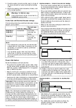
1. Fix the transducer mounting template to the
selected location, using masking or self-adhesive
tape.
1
Transducer mounting template
2
Waterline
3
Mounting away from propeller
2. Ensure the template is parallel to the waterline.
3. Drill 2 x holes for the adjustment slot screws as
indicated on the template.
Note:
Do NOT drill the third mounting hole at this
stage.
4. Fill the 2 holes with marine grade sealant.
5. Using a pozi-drive screw driver and the screws
provided, secure the transom mount bracket
using the 2 adjustment slots.
Note:
The third locking screw is not used until the
transducer has been successfully tested.
4.2 Mounting the transducer
The transducer must be mounted on the transom
using the mounting bracket provided. The steps
below describe the initial mounting steps required
in order to test your transducers performance.
After testing the transducer you must inish the
mounting following the instructions in the
Finishing
the transducer mounting
section.
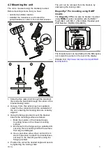
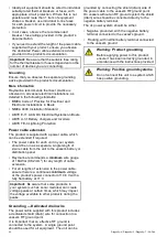
1. Feed the transducer cable between the posts on
the mounting bracket as shown.
2. Slide the ratchet arm into the guide on the top of
the transducer, ensuring it locks in place.
3. Hold the ratchet plate in place on the ratchet arm
as shown.
4. Insert the ratchet arm between the mounting
bracket posts, aligning the center hole with the
holes in the posts.
5. Slide the M5 washer and then the compression
washer onto the ratchet bolt.
6. Slide the ratchet bolt through the mounting
bracket assembly.
7. Insert the M5 locking nut into the captive housing
on the mounting bracket.
8. Using a 4 mm Hex wrench (allen key) tighten
the ratchet bolt until the ratchet mechanism is
engaged but can still be adjusted by hand.
9. Position the transducer so that the bottom face of
the transducer will be parallel with the waterline
and tighten the ratchet bolt.
The transducer position will be adjusted further
during testing.
30
Dragonly–4 / Dragonly–5 / Dragonly–7 / Wi–Fish
Содержание E70290
Страница 2: ......
Страница 4: ......
Страница 12: ...12 Dragonly 4 Dragonly 5 Dragonly 7 Wi Fish ...
Страница 18: ...18 Dragonly 4 Dragonly 5 Dragonly 7 Wi Fish ...
Страница 34: ...34 Dragonly 4 Dragonly 5 Dragonly 7 Wi Fish ...
Страница 42: ...42 Dragonly 4 Dragonly 5 Dragonly 7 Wi Fish ...
Страница 108: ...108 Dragonly 4 Dragonly 5 Dragonly 7 Wi Fish ...
Страница 112: ...112 Dragonly 4 Dragonly 5 Dragonly 7 Wi Fish ...
Страница 122: ...122 Dragonly 4 Dragonly 5 Dragonly 7 Wi Fish ...
Страница 126: ...126 Dragonly 4 Dragonly 5 Dragonly 7 Wi Fish ...
Страница 132: ...132 Dragonly 4 Dragonly 5 Dragonly 7 Wi Fish ...
Страница 133: ...Chapter 16 Spares and accessories Chapter contents 16 1 Spares Accessories on page 134 Spares and accessories 133 ...
Страница 135: ......

