background image

FLIR


DM92


USER


GUIDE


Document


Identifier:


DM92

en

US_AB


17

5.11


Extended


Functionality


In


addition


to


the


basic


measurements,


the


meter


can


be


set


to


different


modes


for


extended


functionality.


5.11.1


Selecting


the


Mode


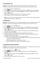
The


mode


icons


applicable


for


the


selected


measurement


type


are


displayed


in


the


lower


part


of


the


display.


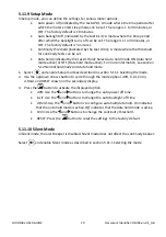
When


a


mode


is


enabled,


the


icon


is


framed.


Figure


5.2


Mode


icons


(AC


voltage


measurements):


Peak


mode


and


Silent


mode


are


enabled.


1.


Press


the


or


button


to


navigate


to


the


desired


mode


icon.


The


currently


selected


icon


will


flash.


2.


Press


the


button


to


enable


the


selected


(flashing)


mode.


3.


Use


the


or


buttons


to


step


through


the


mode


options.


Refer


to


the


section


related


to


the


specific


mode


for


detailed


instructions.


4.


Press


the


button


to


disable


the


selected


(flashing)


mode.


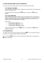
5.11.2


VFD


Mode


(ACV


and


ACA


only)


In


VFD


(variable

frequency


drive)


mode,


high

frequency


noise


is


eliminated


from


the


voltage


measurement


through


the


use


of


a


low

pass


filter.


VFD


mode


is


available


when


measuring


AC


voltage


or


AC


current.


1.


Select


and


enable


VFD


mode


as


described


in


section


5.11.1


Selecting


the


Mode.


5.11.3


Peak


Mode


(ACV


and


ACA


only)


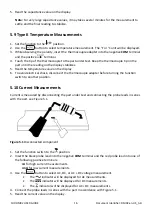
In


Peak


mode,


the


meter


captures


and


displays


the


positive


and


negative


peak


values,


and


updates


only


when


a


higher/lower


value


is


registered.


1.


Select


and


enable


Peak


mode


as


described


section


5.11.1


Selecting


the


Mode.


2.


Press


the


or


button


to


toggle


between


the


display


of


Peak


Max


and


Peak


Min.


In


Peak


Max


mode,


the


indicator


is


displayed.


In


Peak


Min


mode,


the


indicator


is


displayed.


1.


Press


the


button


to


pause


the


Peak


mode.


Press


again


to


continue.


5.11.4


Min/Max/Avg


Mode


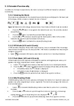
In


Min/Max/Avg


mode,


the


meter


captures


and


displays


the


minimum


or


maximum


values


and


updates


only


when


a


higher/lower


value


is


registered.


The


meter


also


averages


the


total


sum


of


all


recorded


values.


1.


Select


and


enable


Min/Max/Avg


mode


as


described


in


section


5.11.1,


Selecting


the


Mode.


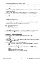
2.


Press


the


or


button


to


cycle


through


the


minimum,


maximum,


and


average


reading


displays.


The


corresponding


icons


are


displayed:


,

,


or


3.


Press


the


button


to


pause


the


Min/Max/Avg


mode.


Press


again


to


continue.


Содержание DM92

Страница 1: ...USER MANUAL FLIR MODEL DM92 True RMS Industrial Multimeter...

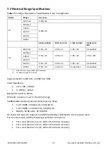
Страница 2: ...Function Buttons Selector Pad and Rotary Switch 9 4 4 Display Description 10 4 5 Display Icons and Indicators 10 5 OPERATION 13 5 1 Powering the Meter 13 5 2 Auto Manual Select Mode 13 5 3 Auto Manua...

Страница 3: ...tery Replacement 21 6 3 Fuse Replacement 21 6 4 Disposal of Electronic Waste 21 7 SPECIFICATIONS 22 7 1 General specifications 22 7 2 Electrical Range Specifications 23 8 TECHNICAL SUPPORT 28 9 WARRAN...

Страница 4: ...herein are used for identification only and are the property of their respective owners 1 2 Quality Assurance The Quality Management System under which these products are developed and manufactured ha...

Страница 5: ...ge If you do not do this damage to the instrument and injury to persons can occur Do not replace the batteries before you remove the test leads This can cause damage to the instrument and can cause in...

Страница 6: ...mage to the protection This symbol adjacent to another symbol or terminal indicates that the user must refer to the manual for further information This symbol adjacent to a terminal indicates that und...

Страница 7: ...e service 3 1 Key Features 4000 40 000 counts extra large digital dual display Auto selection AC DC in voltage and current modes On screen menu selection and navigator key drive Variable frequency dri...

Страница 8: ...low 7 EXIT Button 8 HOLD Lock Button 9 Work Light Button 10 Rotary Function Switch 11 Positive Probe Input Jack for A Current 12 Positive Probe Input Jack for mA Current 13 COM negative Probe Input Ja...

Страница 9: ...The meter can measure current through the probe inputs 4 3 Function Buttons Selector Pad and Rotary Switch Use this button to select Auto select or Manual select mode see section 5 2 Auto Manual sele...

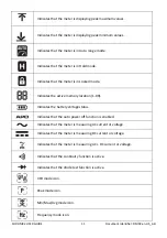
Страница 10: ...es the reading on the main display 4 5 Display Icons and Indicators Indicates that the meter is measuring stabilized voltage Indicates that the measured voltage is greater than 30 V AC or DC Indicates...

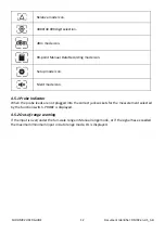
Страница 11: ...ocked mode Indicates the active memory location 1 99 Indicates the battery voltage status Indicates that the auto power off function is enabled Indicates that the meter is measuring AC current or volt...

Страница 12: ...icon Silent mode icon 4 5 1 Probe Indicator When the probe leads are not plugged into the correct jack sockets for the measurement selected by the function switch PROBE is displayed 4 5 2 Out of rang...

Страница 13: ...inactivity see section 5 11 9 Setup mode The meter beeps three times 10 seconds before powering off Press any button or turn the Rotary Switch to prevent the meter from powering off The auto power of...

Страница 14: ...lack probe lead into the negative COM terminal and the red probe lead into the positive terminal 3 Use the button to select AC DC or AC DC voltage measurement The indicator will be displayed for AC me...

Страница 15: ...or will be displayed 3 Insert the black probe lead into the negative COM terminal and the red probe lead into the positive terminal 4 Touch the tips of the probe across the diode or semiconductor junc...

Страница 16: ...isplay 6 To avoid electrical shock disconnect the thermocouple adapter before turning the function switch to another position 5 10 Current Measurements Current is measured by disconnecting the part un...

Страница 17: ...pass filter VFD mode is available when measuring AC voltage or AC current 1 Select and enable VFD mode as described in section 5 11 1 Selecting the Mode 5 11 3 Peak Mode ACV and ACA only In Peak mode...

Страница 18: ...In dBm mode the meter displays AC voltage measurements in dB or dBm on the secondary display dB and dBm are defined as follows dB 20 log VAC 1 dBm 20 log VAC 0 7746 1 Select and enable dBm mode as de...

Страница 19: ...active For more information see section 5 12 Normal hold mode and Auto hold mode 1 Select and enable Setup mode as described in section 5 11 1 Selecting the mode 2 Use the up down arrows button to cyc...

Страница 20: ...ue The current reading is displayed on the main display The held reading on the secondary display will not change unless the difference between this held reading and any new reading is greater than 50...

Страница 21: ...before it displays an out of tolerance voltage 1 To avoid electrical shock disconnect the meter if connected to a circuit remove the probe from the terminals and set the function switch to the OFF pos...

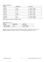
Страница 22: ...F 10 C to 30 C 85 RH 86 F to 104 F 30 C to 40 C 75 RH 104 F to 122 F 40 C to 50 C 45 RH Storage Temperature RH 22 F to 140 F 30 C to 60 C 0 80 RH batteries not fitted Temperature Coefficient 0 1 x spe...

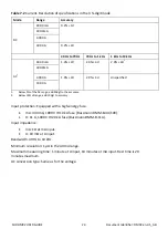
Страница 23: ...cified 1 Below 10 or range add 10d to accuracy 2 Frequency range 1k to 2k Hz Input protection 1000 V DC or 1000 V AC RMS Input impedance mV 1 M 100 pF V 10M 100 pF Bandwidth 40 Hz to 20kHz Minimum res...

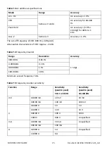
Страница 24: ...ied 10 00 A 1 Below 5 of the AC range add 20dgt to the accuracy 2 Below 10 of range add 10 dgt to accuracy Input protection Equipped with a high energy fuse mA 440 mA 1000 V IR 10 kA fuse Bussmann DMM...

Страница 25: ...stic of VFD Approx 24 dB Table 7 4 Frequency Counter Range Resolution Accuracy 400 00 Hz 0 01 Hz 5 dgt 4 0000 kHz 0 1 Hz 40 000 kHz 1 Hz 100 00 kHz 10 Hz Minimum sensed frequency 5 Hz Table 7 5 Freque...

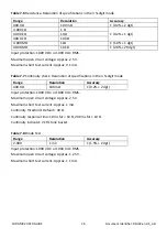
Страница 26: ...pprox 0 1 mA Table 7 7 Continuity check Resolution of specifications in the 3 digit mode Range Resolution Accuracy 400 0 100 m 0 2 2 dgt Input protection 1000 V DC or 1000 V AC RMS Maximum open circui...

Страница 27: ...dgt 400 0 F 100 nF 0 9 2 dgt 4 000 mF 1 F 1 2 20 dgt 40 00 mF 10 F 2 0 20 dgt Input protection 1000 V DC or 1000 V AC RMS Table 7 10 Temperature Range Resolution Accuracy 328 F to 2192 F 0 1 F 1 0 36...

Страница 28: ...Warranty are MR7x CM7x CM8x DM9x IM7xand VP5x not including accessories which may have their own warranty 3 WARRANTY PERIODS For purposes of the The Limited Lifetime Warranty Lifetime is defined as s...

Страница 29: ...ttp www flir com to request an evaluation and obtain an RMA Purchaser is solely responsible for complying with all RMA instructions provided by FLIR including but not limited to adequately packaging t...

Страница 30: ...CEMENT To be eligible for warranty repair or replacement Purchaser must notify FLIR within thirty 30 days of discovering of any apparent defect in materials or workmanship Before Purchaser may return...

Страница 31: ...7070 USA Telephone 1 503 498 3547 Customer Support Technical Support Website http support flir com Technical Support Email T MSupport flir com Service and Repair Email Repair flir com Customer Support...

Отзывы: