


Technical Description and Installation Manual
GigaFlex
18
Although the unit can be located either vertically or horizontally, the vertical position is preferred
because this enables a better airflow.
A comfort clip
FG-RAIL-ComfortClip-Orion2/3
can be purchased separately. It simplifies the
device installation on a DIN-rail.
4.4
Connecting Power Input and Protective Ground
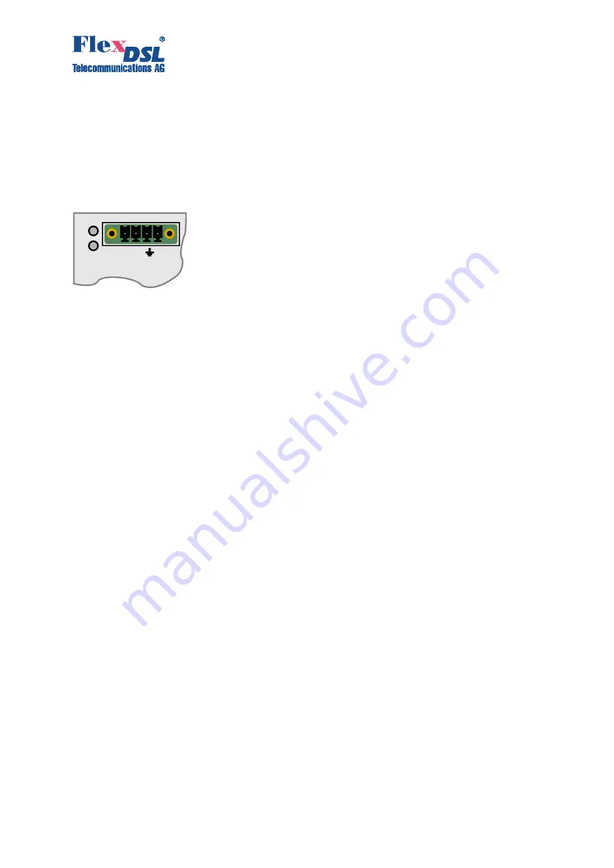
Connect the power, for example -24VDC, to the power input terminal as it is shown on Figure 4-2.
Please refer to Chapter 6.3 for Input Power Supply specification.
Figure 4-2. Power Connector
Be sure that the rail where you mount the GigaFlex device is proper connected to the Protective
Earth. If you are not sure about a proper Protective Earth connection through the DIN-rail
mechanics, please connect the Protective Earth to the corresponding connector on Figure 4 2.
If you ave si gle power supply, it’s recomme ded to co ect -V1 and -V2 with a wire bridge.
The Unit will not show you an alarm indicating that one power supply input is not present.
4.5
Connecting Interface Cables
Connect all required interface cables. Use Table 3-1 as a reference for wiring.
Plug SFP modules and connect fiber cables.
Connect a PC with USB cable to the LCT jack and start a Terminal emulation program. The Serial
port settings are:
•
Rate: 9600
•
Bits: 8
•
Parity: None
•
Stop bits: 1
•
Flow Control: Off
4.6
Power on the Device
Power on the device. The LEDs 1 and 2 on Figure 4-2 should be red during boot process.
Refer to the GigaFlex Configuration Manual for configuration steps and examples.
VDC
V V


