7
7. THE TAILPIECE (PART J)
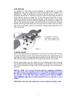
Take a look at the bridge and tailpiece hardware and distinguish the
difference between the bridge studs and the tailpiece studs. The tailpiece
studs have a much larger set screw.
Install the tailpiece first. Separate the tailpiece mounting parts from the
threaded bushings. These bushings must be driven in place in the two holes
closest to the rear of the guitar body. It will be necessary to ground the
electronic circuitry to the tailpiece. The control cavity is at the back of the
guitar body. On the inside wall of this cavity you will see a small 1/8” hole.
Run the stripped end of the ground wire through this hole until it emerges in
the hole drilled for the tailpiece bushing. Form the naked wire into a loop,
wrap it around the bushing and tap the bushing tightly into the hole. This will
ground the circuit.
- Installing the tailpiece bushings may be done with a plastic headed mallet or
place a small piece of wood on top of the bushing to prevent damage and tap
the bushing in place with an ordinary hammer. Now screw the tailpiece
mounting screws back into the bushings.
8. THE BRIDGE (PART J)
Now tap the bridge bushings into place and screw in the bridge mounting
studs. Attach the bridge.
9. OUTPUT JACK (PART C)
The output jack (once wired) will be attached to the neck pickup tone control
pot by a blue grounding wire. Find the wire running from the pickup selector
switch and solder it to the wire on the output jack. Push the output jack and its
wire through the 7/8” hole that has been drilled between the control cavity and
the edge of the body.
Attach the output jack plate (Part C) to the output jack using the washer and
nut provided. Screw the output jack plate to the body with the two 3/8” screws
provided.
10. BACK PLATE (PART F)
Carefully stuff all of the wiring into the control cavity and attach the back plate
using the screws provided.
11. TUNERS (PART K)
Attach the six tuning machines to the headstock of the guitar putting a washer
beneath each threaded bushing. A small set screw is put in place to prevent
the tuner from rotating.
Содержание SPR01
Страница 11: ...10...


