background image

FTS 371 SMART USER MANUAL 

Flash Technology, LLC 

Revision 4 – 9/7/2021 

17 

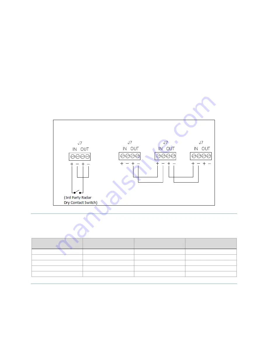
When the RADAR configuration switch is placed in the ON position, an external device such as a radar system may 
inhibit the output of the beacon. Wire the dry contact from the external device to connector J7 terminals with IN+ 
and OUT+ as shown below and jumper the terminals IN- to OUT-. The fail-safe design requires a closed contact to 
inhibit the output of the beacon so the beacon is on if the contact is open and off if closed.  

For primary/secondary synchronization, set the RADAR configuration switch to the OFF position and wire the J7 
SYNC connector to other controllers as shown below, primary OUT+ and OUT- to secondary #1 IN+ and secondary 
#1 IN-, etc. Each secondary must have its secondary configuration dipswitch set to ON and its flash configuration 
set to match the primary: flash type (efficiency/legacy), flash spec (FAA/ICAO) and beacon and marker 
flashing/steady. Secondary units with nonmatching configuration will not flash in unison with the system. A 
photodiode is connected to the primary controller only, not the secondary unit. 

Note:

 The EXT SYNC LED is on at the beginning of SYNC pulse and off at end of SYNC pulse on both primary and 

secondary. The secondary’s EXT SYNC LED will flash ON only if properly wired to primary so is a good 
troubleshooting check. 


CATENARY OPERATION 

For catenary operation, wire the systems as shown above and set the configuration switches as in the table below. 
Note that for the Middle level, both CAT T and CAT B switches should be set to OFF. 


Primary (CAT TOP) 

Secondary #1 (CAT MID) 

Secondary #2 (CAT BOT) 

SECONDARY 

OFF 

ON 

ON 

RADAR


OFF


OFF 

OFF 

60FPM


ON


ON 

ON 

CAT T


ON


OFF 

OFF 

CAT B


OFF


OFF 

ON 

GPS SYNCHRONIZATION 

For GPS synchronization, the optional GPS Sync Kit must be installed including external GPS antenna mounting. 
Refer to the FTS 371 GPS Sync Kit (P/N 1370285) Installation Instructions for details.  

The portion outlined in red shows the location of the FTS 371 GPS OPTION PCB PN 2433000 on the controller PCB. 

Primary Dry Contact 

Radar Input 

Primary and Secondary Synchronization 

Primary 

Secondary #1 

Secondary #2 

Содержание Vanguard Red FTS 371 SMART

Страница 1: ...ology 332 Nichol Mill Lane Franklin TN 37067 flashtechnology com 1 615 503 2000 1 800 821 5825 Vanguard Red FTS 371 SMART Medium Intensity Red LED Obstruction Lighting System Reference Manual Part Number F7913800 ...

Страница 2: ...he equipment included in this system meets or exceeds requirements for ICAO Annex 14 Sixth Edition for Medium intensity obstacle lights Types B and C as well as Low intensity obstacle light Type B DISCLAIMER While every effort has been made to ensure that the information in this manual is complete accurate and up to date Flash Technology assumes no liability for damages resulting from any errors o...

Страница 3: ...all times when you expose circuits and components and when you operate maintain or service this equipment AVOID TOUCHING LIVE CIRCUITS Avoid touching any component or any part of the circuitry while the equipment is operating Do not change components or make adjustments inside the equipment with power on DO NOT DEPEND ON INTERLOCKS Never depend on interlocks alone to remove unsafe voltages Always ...

Страница 4: ...TS 371 FTC SMART DC FTS 371 FTS SMART DC 24 48V 9 Flashhead Beacon FTS 371 FH AC FTS 371 FH DC 24V FTS 371 FH DC 48V 9 Markers MKR 371 MKR 372 IR Series 10 Markers MKR 371 OL2 MKR 372 IR OL2 Series 10 Section 2 Outline Mounting and Installation Instructions 11 Unpacking 11 Tools 11 Controller Installation and Grounding 11 L 864 Flashhead Beacon Installation and Grounding 12 OL2 Installation and Wi...

Страница 5: ...onent Removal and Replacement 38 FTS 371 FTC SMART Controller 38 FTS 371 FH AC L 864 LED 39 Firmware Upgrades 39 Preparing the USB Drive 39 Upgrading Firmware 39 Downgrading Firmware 40 Additional Notes 40 Section 4 Operating Instructions 41 Controller 41 Manual Override Option 41 Tower Configurations 41 Controller Configuration Switch Definitions 41 Marker Configuration Switch 42 Alarm Indicators...

Страница 6: ...tallation Wiring 31 Figure 11 FTS 371 Typical A1 Tower View 32 Figure 12 Controller FTS 371 SMART DC Connection Diagram 33 Figure 13 Controller FTS 371 SMART DC Connection Diagram 34 Figure 14 Flashhead Beacon FTS 371 FH DC Connection Diagram 35 Figure 15 FTS 371 SMART DC Typical FAA Type A0 Installation Wiring 36 Figure 16 FTS 371 SMART DC Typical FAA Type A1 Installation Wiring 37 LIST OF TABLES...

Страница 7: ...FTS 371 SMART USER MANUAL Flash Technology LLC Revision 4 9 7 2021 7 Table 4 5 Troubleshooting Symptoms and Resolutions 45 Table 5 1 Replacement Parts 46 ...

Страница 8: ...d are available only with the aluminum enclosure The FTS 371 SMART system is designed to meet FAA ICAO and Transport Canada regulations and to be utilized for their corresponding valid tower lighting configurations Table 1 1 System and Component Model Combinations System Controller Beacon Markers FTS 371 SMART AC FTS 371 FTC SMART AC FTS 371 FH AC IR 0 to 2 MKR 371 0 to 8 MKR 372 IR 0 to 8 FTS 371...

Страница 9: ...MART AC FTS 371 FTC SMART DC 3 8 Watts 1 3 Watts Flash Rate Options Flashes Per Minute Steady Burn 20 30 40 60 Alarm Relay Contact Rating 5 Amp 120V AC 5 Amp 24V DC Isolated contacts Protection Rating IP65 NEMA 4X FLASHHEAD BEACON FTS 371 FH AC FTS 371 FH DC 24V FTS 371 FH DC 48V Table 1 3 Beacon Specifications Parameter Specification Physical Dimensions 15 75 diameter x 7 5 400 mm diameter x 190 ...

Страница 10: ...6 9 Watts MKR 372 L810 IR Flashing 1 5 Watts Beam Spread Horizontal 360 deg Vertical 10 deg Aerodynamic Wind Area 24 75 in2 Protection Rating IP65 NEMA 4X MARKERS MKR 371 OL2 MKR 372 IR OL2 SERIES Table 1 5 OL2 Marker Specifications Parameter Specification Physical Dimensions 11 25 x 5 0 x 8 75 279 4 mm x 127 mm x 222 25 mm NPT Coupling Weight 5 40 lbs 2 45 kg Intensity Steady 32 5 ECD 25 Operatin...

Страница 11: ...nt for access during installation maintenance and servicing Allow space for airflow around the controller Recommended 3 4 of space allowed on each side of the controller Flash Technology does not furnish mounting hardware unless it is ordered as part of an installation kit Flash Technology recommends using flexible conduit for all cable runs with the exception of the beacon cable and jacketed grou...

Страница 12: ...vel in both directions Fully tighten the hardware and verify that the beacon is level If necessary loosen the mounting hardware and repeat Step 5 until the beacon is level with the hardware fully tightened 7 Connect a minimum 8 AWG grounding wire to the pre installed grounding lug on the beacon base exterior Connect the other end of the wire directly to tower steel collective buss bar or the custo...

Страница 13: ...out installation wiring required for your installation Important If installation drawings prepared specifically for your site disagree with information provided in this manual the site installation drawings should take precedence Consult any site specific installation wiring diagrams supplied with your equipment All installation wiring should have an insulation rating of 600 volts Wire size for th...

Страница 14: ...inch separation from the flange and the cable AM HOT TOWER WIRING On AM hot towers wire the beacon markers and controller as described in this section except for the following On the cable between the controller and beacon do not connect the ground conductor in the controller or the beacon FLASHHEAD BEACON WIRING For AC powered systems see beacon wiring in Figure 7 page 29 and typical installation...

Страница 15: ...kwise On DC systems observe polarity of input voltage and connect positive to DC and negative to DC There is one replaceable input power fuse located at F1 To remove the fuse disconnect power then push in and turn counterclockwise BEACON AND MARKER CONNECTIONS On the FTS 371 FTC SMART controller the beacon connections are at J2 and marker connections are at J3 For AC powered systems up to two FTS ...

Страница 16: ...tion switches and jumpers configure alarming DRY CONTACT MONITORING AND PHOTODIODE CONNECTIONS Find the dry contact monitoring connections on J4 and J5 The FTS 371 controller allows the option to have a BEACON MARKER and PHOTODIODE alarm point available for external monitoring Also included is the MODE relay connections that allow remote notification of mode change via a dry contact The photodiode...

Страница 17: ...nmatching configuration will not flash in unison with the system A photodiode is connected to the primary controller only not the secondary unit Note The EXT SYNC LED is on at the beginning of SYNC pulse and off at end of SYNC pulse on both primary and secondary The secondary s EXT SYNC LED will flash ON only if properly wired to primary so is a good troubleshooting check CATENARY OPERATION For ca...

Страница 18: ... not lit check that antenna has an unobstructed view of the sky OPEN Lit red indicates cable or antenna not connected or damaged SHORT Lit red indicates cable or antenna is shorted and defective RS 485 MODBUS RTU COMMUNICATION Advanced monitoring of the FTS 371 SMART controller is available by RS 485 Modbus RTU communication interface available at connector J6 The FTS 371 SMART system controllers ...

Страница 19: ...neath the controller where it could be shadowed Photodiode installation is water tight AM Towers Only If the AM tower is hot do NOT connect the ground wires to the beacon power connector or the controller beacon power connector Table 2 3 Before Applying Power Checklist Examine installation drawings Verify incoming service voltage is the value stated on the ID plate Ensure the unit is wired accordi...

Страница 20: ...he Test in Progress LED begins flashing then release the button The Test in Process LED will blink throughout the entire lighting inspection as an indication that the LI is still underway The LI may be cancelled at any time by pressing the inspection button for 3 seconds 2 Press the white inspection button one quick press to activate the first alarm 3 If beacons are configured BCN ON OFF configura...

Страница 21: ...otodiode control b Cover the photodiode to block it from all light and wait up to 60 seconds c Verify that the STATUS LEDs show that the system is now in NIGHT mode d Verify that the beacon and or marker s connected to the controller are on and operating as programmed i Uncover the photodiode to allow light to strike it or shine a light on it With no alarms or errors verify that after a delay 1 Th...

Страница 22: ...2021 22 Figure 1 Controller FTS 371 SMART Poly Enclosure Mounting and Outline A A A B A B 9 36 237 74 11 69 296 93 FRONT VIEW RIGHT SIDE VIEW BOTTOM VIEW 10 75 273 05 7 01 178 05 6 00 152 4 KNOCKOUT TABLE LETTER QTY A B 0 875 22 4 1 093 27 8 4 2 KNOCKOUT SIZE DIA ...

Страница 23: ...A A A A A B B HINGE ENCLOSURE FRONT VIEW ENCLOSURE BOTTOM VIEW ENCLOSURE RIGHT VIEW 3 00 76 20 5 00 127 00 10 50 266 70 14 92 378 97 13 78 350 01 16 10 408 94 Ø0 50 12 70 2 PLACES 4 91 124 79 KNOCKOUT TABLE ALL HOLES KNOCKOUT FROM INSIDE LETTER QTY A B 0 875 22 4 1 093 27 8 5 2 SHADED HOLES REPRESENT FACTORY REMOVED KNOCKOUTS KNOCKOUT SIZE DIA ...

Страница 24: ...Revision 4 9 7 2021 24 Figure 3 Marker MKR 371 MKR 372 IR series mounting and outline view 9 00 228 6 7 00 177 8 0 38 9 65 2 64 67 06 1 45 36 83 38 9 65 3 4 14 NPS 2 75 69 85 1 4 20 UNC TYP OF 3 1 20 30 48 1 20 30 48 1 03 26 16 1 63 41 40 2 13 54 10 ...

Страница 25: ...FTS 371 SMART USER MANUAL Flash Technology LLC Revision 4 9 7 2021 25 Figure 4 OL2 mounting and outline view ...

Страница 26: ...FTS 371 SMART USER MANUAL Flash Technology LLC Revision 4 9 7 2021 26 Figure 5 Flashhead Beacon FTS 371 FH mounting and outline view 15 75 400 7 5 190 5 ...

Страница 27: ...FTS 371 SMART USER MANUAL Flash Technology LLC Revision 4 9 7 2021 27 Figure 6 Photodiode PHD 516 mounting and outline view 4 27 108 458 1 2 NPT 1 31 33 274 2 02 51 308 ...

Страница 28: ...021 28 Figure 7 Controller FTS 371 FTC SMART AC Connection Diagram BEACON ON OFF BEACON QTY 1 2 BEACON FL ST MARKER ST FL EFFICIENCY LEGACY FAA ICAO PD ALARM ON OFF SECONDARY OFF ON AUX INPUT OFF ON OPTION 20FPM 30FPM 40FPM 60FPM CAT T CAT B AUX 1 AUX 2 AUX 3 AUX 4 ...

Страница 29: ...FTS 371 SMART USER MANUAL Flash Technology LLC Revision 4 9 7 2021 29 Figure 8 Flashhead Beacon FTS 371 FH AC Connection Diagram ...

Страница 30: ...PM CAT T CAT B AUX 1 AUX 2 AUX 3 AUX 4 MKR 371 MKR 372 CONNECTIONS DETAIL A PHD 516 PHOTODIODE NOTE ONLY SYSTEMS USING MKR 372 ARE CERTIFIED UNDER FAA AC 150 5345 43J BEACON ON OFF BEACON QTY 1 2 BEACON FL ST MARKER ST FL EFFICIENCY LEGACY FAA ICAO PD ALARM ON OFF SECONDARY OFF ON AUX INPUT OFF ON OPTION Cut off marker cable shield at housing Do not connect cable shield to marker or marker housing...

Страница 31: ...1 AUX 2 AUX 3 AUX 4 MKR 371 MKR 372 CONNECTIONS DETAIL B PHD 516 PHOTODIODE FH 371 AC CONNECTIONS DETAIL A NOTE ONLY SYSTEMS USING MKR 372 ARE CERTIFIED UNDER FAA AC 150 5345 43J MKR 371 MKR 372 MKR 371 MKR 372 MKR 371 MKR 372 BEACON ON OFF BEACON QTY 1 2 BEACON FL ST MARKER ST FL EFFICIENCY LEGACY FAA ICAO PD ALARM ON OFF SECONDARY OFF ON AUX INPUT OFF ON OPTION Cut off marker cable shield at hou...

Страница 32: ...FTS 371 SMART USER MANUAL Flash Technology LLC Revision 4 9 7 2021 32 Figure 11 FTS 371 Typical A1 Tower View ...

Страница 33: ...2021 33 Figure 12 Controller FTS 371 SMART DC Connection Diagram 20FPM 30FPM 40FPM 60FPM CAT T CAT B AUX 1 AUX 2 AUX 3 AUX 4 BEACON ON OFF BEACON QTY 1 2 BEACON FL ST MARKER ST FL EFFICIENCY LEGACY FAA ICAO PD ALARM ON OFF SECONDARY OFF ON AUX INPUT OFF ON OPTION ...

Страница 34: ...USER MANUAL Flash Technology LLC Revision 4 9 7 2021 34 Figure 13 Controller FTS 371 SMART DC Connection Diagram 20FPM 30FPM 40FPM 60FPM CAT T CAT B AUX 1 AUX 2 AUX 3 AUX 4 VIN VIN VIN VIN REMOTE VOUT VOUT TRIM TRIM ...

Страница 35: ...FTS 371 SMART USER MANUAL Flash Technology LLC Revision 4 9 7 2021 35 Figure 14 Flashhead Beacon FTS 371 FH DC Connection Diagram ...

Страница 36: ...Wiring MKR 371 MKR 372 OL 2 FIXTURE SEE DETAIL A PHD 516 PHOTODIODE 20FPM 30FPM 40FPM 60FPM CAT T CAT B AUX 1 AUX 2 AUX 3 AUX 4 MKR 371 MKR 372 CONNECTIONS DETAIL A NOTE ONLY SYSTEMS USING MKR 372 ARE CERTIFIED UNDER FAA AC 150 5345 43J Cut off marker cable shield at housing Do not connect cable shield to marker or marker housing ...

Страница 37: ...ODIODE JUNCTION BOX SEE DETAIL B FH 371 DC CONNECTIONS DETAIL A 20FPM 30FPM 40FPM 60FPM CAT T CAT B AUX 1 AUX 2 AUX 3 AUX 4 MKR 371 MKR 372 CONNECTIONS DETAIL B NOTE ONLY SYSTEMS USING MKR 372 ARE CERTIFIED UNDER FAA AC 150 5345 43J MKR 371 MKR 372 MKR 371 MKR 372 MKR 371 MKR 372 MKR 371 MKR 372 Cut off marker cable shield at housing Do not connect cable shield to marker or marker housing ...

Страница 38: ...omponent or other abnormal condition Table 4 5 Troubleshooting page 45 contains information to help locate the cause of a problem COMPONENT REMOVAL AND REPLACEMENT Note the wiring connections and wire colors when you remove wires from their connections Replace them exactly as they were FTS 371 FTC SMART CONTROLLER PCB1 2151500 FTS 371 FTC SMART AC 2153500 FTS 371 FTC SMART DC 2153510 FTS 371 FTC S...

Страница 39: ... order Be sure to reconnect cable ground conductor to PCB or flashhead base connection point FIRMWARE UPGRADES PREPARING THE USB DRIVE The FTS 371 SMART controller is capable of having its firmware upgraded via a USB drive Firmware files can be found on Flash Technology s website flashtechnology com software and must then be loaded to a USB drive The firmware file must be stored in the root direct...

Страница 40: ... this mode simply fail the firmware upgrade process by removing the USB drive while the firmware upgrade is being performed 2 Now follow the firmware upgrade process ADDITIONAL NOTES Flash Technology advises removing the USB drive once the firmware is updated However a failure to do this will not result in the firmware being updated with each power cycle The controller will recognize that the firm...

Страница 41: ... DAY MODE or NIGHT MODE will blink during a mode override When the switch is in the center position the controller s mode will be determined by the connected photodiode s reading of ambient lighting TOWER CONFIGURATIONS The configuration switch bank offers the ability to program the controller for a variety of installation situations The system will come pre programmed from the factory but if repr...

Страница 42: ... per minute 40FPM No selection Sets system for 40 flashes per minute 60 FPM No selection Sets system for 60 flashes per minute CATENARY TOP CATENARY MID CATENARY BOTTOM ON OFF OFF OFF OFF ON CAT T CAT B AUX 1 AUX 4 Factory reserved currently unused MARKER CONFIGURATION SWITCH Switch Label Switch Position Marker 0 No Markers 1 to 8 Number of Connected Markers The CONFIG ERROR LED will be on in case...

Страница 43: ... Confirm that the MARKER configuration dial is set to the actual number of connected markers 2 Replace the failed marker lights PHOTODIODE The controller has detected the absence of a mode change in the last 19 hours This could indicate the failure of the photodiode 1 Visually confirm that the photodiode is properly connected 2 Perform the Checkout Procedure page 19 3 If the alarm persists replace...

Страница 44: ...on LED strings turn off until the next day to night transition or after removal of applied power for more than 30 seconds ICAO On when the board is running in ICAO mode Off in FAA mode FLASHHEAD BEACON SWITCH BANK When the FTS 371 FH is not connected to an FTS 371 FTC controller the switch bank will be used to program the beacon for a variety of installation situations However when an FTS 371 cont...

Страница 45: ...CB1 Failure Beacon marker alarm 1 Normal if a light fixture is out 2 PCB1 is configured incorrectly for the connected lighting equipment False alarm 1 Check for correct alarm connections normally open NO contacts close on alarm normally closed NC contacts open on alarm 2 PCB1 failure Lights do not flash 1 Confirm that the BCN and or MKR flash configuration settings are set to FL flashing and not S...

Страница 46: ...510 FTS 371 FTC SMART AC Power Supply PWR SUP FTS 371 SMART AC FTC 5371110 FTS 371 FTC SMART DC 24 48V Power Supply POWER SUPPLY FTS 371 SMART 24 48V 5371125 FTS 371 FTC SMART AC or DC PCB1 F1 F2 Fuse 10A 11000016013 FTS 371 FTC SMART AC or DC GPS Board PCB FTS 371 GPS OPTION 2433000T FTS 371 FTC SMART AC or DC GPS Kit FTS 371 GPS SYNC KIT 1370285 FTS 371 FH AC or DC Light Engine FH 370 371 IR Lig...

Страница 47: ...tart the process on sites not requiring detailed troubleshooting Complete the online form at flashtechnology com rma request form NOTE An RMA number must be requested from Flash Technology prior to return of any product No returned product will be processed without an RMA number Failure to follow the below procedure may result in additional charges and delays Any product received without an RMA nu...

Отзывы: