FTS 371 SMART USER MANUAL
Flash Technology, LLC
Revision 4 – 9/7/2021
20
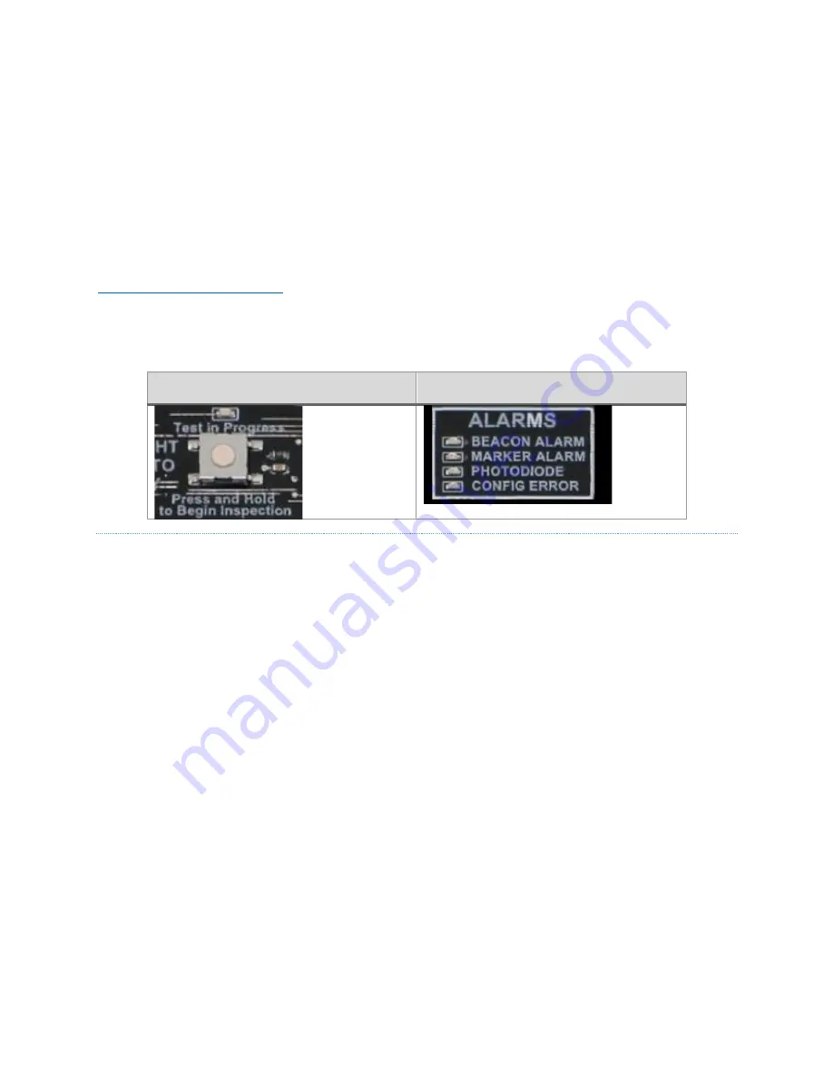
Start the LI by pressing the white Inspection button, which is located in the bottom center of the “Configuration”
box and to the right of the MODE switch. The automated LI first tests the beacon (if configured), then the markers
(if configured) and finally the photodiode alarm. During the beacon and marker tests, the corresponding output is
turned off (beacon or marker turned Off) and the controller confirms that an alarm is properly generated (four
missed flashes are required to trigger an alarm). Then the output is turned back on (beacon or marker turned On)
and the controller confirms that the alarm is properly cleared (four good flashes are required to clear an alarm). If
no beacons or markers are configured, these steps will be skipped and only the photodiode alarm will be tested.
Important!
Before attempting to perform the LI, verify that the PCB configuration switches are properly set
including that the beacon and marker switches match the number of connected beacons and markers. See the
Section 4 - Operating Instructions
(page 41) for details of switch settings.
Important!
During each step of the LI process described below, the technician must confirm that the ALARM LED
comes on and goes off as described. The ALARM LED for each section of the test must come ON and go OFF as
described for a successful lighting inspection.
LI Inspection Button
Alarm Indication LEDs
LIGHTING INSPECTION PROCEDURE
1.
To begin, press and hold the white inspection button for 3+ seconds until the “Test in Progress” LED
begins flashing then release the button. The ‘Test in Process” LED will blink throughout the entire lighting
inspection as an indication that the LI is still underway. The LI may be cancelled at any time by pressing
the inspection button for 3+ seconds.
2.
Press the white inspection button (one quick press) to activate the first alarm.
3.
If beacons are configured (BCN ON/OFF configuration switch is set to ON), the following steps are
performed. If switch is set to OFF, this test is skipped.
a.
Confirm Beacon Alarm - The BEACON ALARM LED will flash as the alarm is being generated
(four missed flashes required). Once the alarm is active the BEACON ALARM LED will be lit
solid. The technician must verify that the BEACON ALARM LED comes on solid.
b.
Clear Beacon Alarm - To restore (clear) the alarm, press the inspection button (one quick
press). Once the alarm is cleared (four good flashes required), the BEACON ALARM LED will
be OFF. The technician must verify that the BEACON ALARM LED goes OFF.
4.
Press the white inspection button (one quick press) to activate the next alarm.
5.
If markers are configured (MARKER # rotary configuration switch is set to a number other than zero), the
following steps are performed. If switch is set to zero, this test is skipped.
a.
Confirm Marker Alarm - The MARKER ALARM LED will flash as the alarm is being generated
(four missed flashes required). Once the alarm is active, the MARKER ALARM LED will be lit
solid. The technician must verify that the MARKER ALARM LED comes ON solid.
b.
Clear Marker Alarm - To restore (clear) the alarm, press the inspection button (one quick
press). Once the alarm is cleared (four good flashes required), the MARKER ALARM LED will
be OFF. The technician must verify that the MARKER ALARM LED goes OFF.


