


Fläkt Woods
3099 US 03.02
21
Specifications are subject to alteration without notice
PUMA (A–F) Rotary heat exchanger
TECHNICAL HANDBOOK
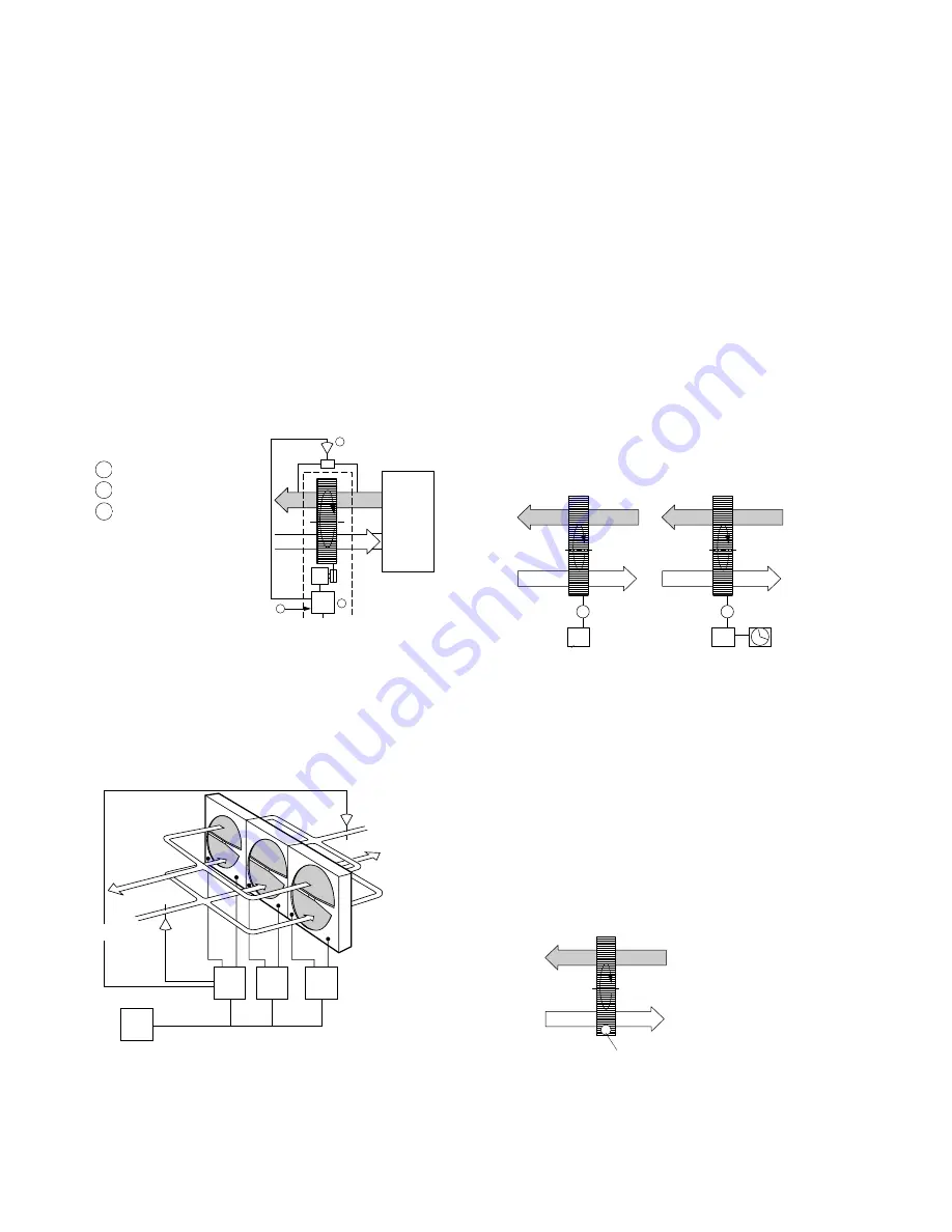
1 Speed controller
2 Differential pressure switch.
3 Control signal
Control
Example 7. Purging operation
Purging operation should be employed when the heat
exchanger rotor is stationary for an extended period of
time in an environment in which the supply or exhaust
air contains dust that may cause clogging.
For the ECONOVENT with variable speed, no time-
switch need be employed. Purging operation is integrated
into the speed controller. The function is switched on
automatically when the rotor is stationary. A timeswitch
(SU) with 24-hour dial is used for the ECONOVENT
with constant speed, and this starts the rotor and runs it
at maximum speed for 0.5–1 hour per 24 hours. Any
dust that may have settled in the rotor passages will then
be blown away by the air flow which is continually
reversed through the rotor. A filter should always be
installed in systems in which the dust is likely to cause
deposits (see page 16).
Variable speed Constant speed
M
RC
RPM
Reglersignal
M
K
SU
Fig. 19
Control signal,
heat recovery
Temperature limit for the drive motor
To ensure effective cooling of the drive motor located
inside the casing, the temperature in the motor compart-
ment should always be lower than +100 °F.
In systems in which the supply or exhaust air is at a
higher temperature than +100 °F, the heat exchanger
should be installed so that the leakage flow is from the
cooler air stream to the warmer air stream. This is achiev-
ed by p1 > p2 and p2 > p4 as shown in Fig. 20 below. If
the supply and exhaust air are both at temperatures above
+100 °F, the motor compartment should be cooled by
means of a separate fan.
As an alternative, the heat exchanger can be supplied
with the drive motor located outside the casing.
p3
p1
p4
p2
Motor
”Varmt” luftflöde
t
≥
+40
°
C
”Kallt” luftflöde
t
≤
+40
°
C
Warmer air at
t
≥
+100 °F
Cooler air at
t
≤
+100 °F
Motor
Fig. 20
Example 5. Frosting monitor
Variable speed: The frosting monitor is used for indicat-
ing frosting in the rotor at very low outdoor temperatures
and high humidity of the exhaust air. If the pressure drop
across the rotor exceeds the value preset on differential
pressure switch 2, the rotor speed will be reduced if the
heat exchanger is running at variable speed.
Constant speed: In the case of a constant-speed heat
exchanger, the rotor is defrosted by the supply air being
by-passed across the rotor via a damper or by the supply
air fan being stopped. The differential pressure switch
indicates when the damper should be opened or when
the fan should be stopped.
Caution. No frosting is permissible in a composite
rotor.
Example 6. Parallel operation
If several rotary heat exchangers are included in a given
air handling system and are thus to be controlled simulta-
neously, each heat exchanger must have its own speed
controller and sensor for the speed detector. On the other
hand, the control signals from the control unit (RC) and
summer case sensors can be connected to only one speed
controller, from which the others are supplied.
Rum
RC
RPM
DM
1
3
2
RC
RPM
RC
RPM
RC
RPM
RC
Frånluft
Tilluft
Fig. 18
Room
Supply air
Exhaust air
Fig. 17
RC = Control unit
RC
RPM
= Speed controller