
MAJOR COMPONENTS
Cabinet
The cabinet is constructed of 18 gauge steel, painted
with a tough powder-coated, scratch-resistant finish.
Holes are provided to facilitate mounting to the ductwork.
Access to the collecting cells and prefilters is through a
hinged door.
The access door is interlocked to cut power to the unit
when opened.
Prefilters
The washable prefilters, measuring 11½ x 20 inches
(29.21 x 50.8 cm) are constructed of multi-layers of
aluminum mesh for maximum filtration of large particles.
Collecting Cells
The dual voltage collecting cells are constructed of
heavy gauge aluminum to resist rust and damage. The
first stage, the ionizing section, is charged at
approximately 7000 VDC. The collecting plates are
alternately grounded and charged at 4600 VDC. The
arrow on the cells indicates the direction of air flow which
must point toward the rear of the unit.
Electrical Compartment
The electrical compartment contains the system
switch, safety interlock, high voltage power board,
transformer, air proving switch and performance indicator
light.
INSTALLATION
Location
The Air Cleaner should be installed to the return air
duct in the living area of the home or office. It can be
installed either in a wall or ceiling, but not in the floor.
This unit will replace the existing return air grille currently
installed to the main return duct. For the unit to perform
properly, all the return air must pass through the
Electronic Air Cleaner.
In a wall installation, the unit must be installed with
the hinge down.
The return duct or transition should end slightly
behind the finished wall or framing. It should be
approximately 1/4 -1/2 inch (.63 - 1.27 cm) larger than the
air cleaner to allow the back of the unit to slip into the duct
when installing.
When the air duct does not fit the Air Cleaner
opening, a gradual transition is recommended to reduce
air turbulence through the Air Cleaner and to increase its
efficiency. There should not be more than 20º of
expansion used for the transition fitting.
Installation
Carefully remove the Air Cleaner from the carton.
Remove the cells and prefilters from the unit. Remove
the access door from the unit by removing the screw on
the end of the retaining link in the enclosure. Lower the
access door and remove the screws securing the hinge to
the enclosure.
Remove the five screws securing the electrical
compartment cover.
The hole in wall or ceiling should be made to fit the Air
Cleaner opening as closely as possible. The opening
should be framed to provide adequate support for the Air
Cleaner. Before mounting the Air Cleaner, cover the
framing and close the opening to within 1/4 in. (.63 cm) of
the dimension of the rear of the enclosure of the Air
Cleaner. Match the finish to the existing wall.
Mount the Air Cleaner into the framed hole and slide
into the duct until the front flange is flush with the wall.
Secure the Air Cleaner to the frame using sheet metal
screws. Do not overtighten screws as this may distort the
enclosure. Once the unit is secured to the wall, the
access door and retaining link can be replaced.
Wiring
Wiring should only be performed by qualified
personnel only. All wiring must comply with all applicable
codes and standards. The voltage of the power source
must match the voltage indicated on the Air Cleaner. The
Air Cleaner should operate ONLY when the system fan is
running. Make sure the Air Cleaner is properly grounded.
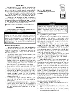
Wire the Air Cleaner directly to the power source. The
APS will power the Air Cleaner when there is sufficient
airflow to activate the sensor.
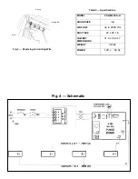
Connect the black lead of the Air Cleaner to the line
side of power source. Connect the white lead to the
neutral side of the power source. Connect the green lead
to ground. See Fig. 3.
SYSTEM CHECK
Perform the following system check before operation.
1. Replace the prefilters and collecting cells. Close
access door and replace thumb screw.
2. Turn Air Cleaner power switch ON. Ensure system
fan is operating. The performance indicator light
should be lit showing that the Air Cleaner is operating.
Note:
There may be some arcing or snapping sounds
from the collecting cells. This is normal when the unit is
new. In about 2 weeks, as the sharp edges of the cells
become smoother, the arcing will disappear.
OPERATION
The Air Cleaner will run as long as there is airflow
through the ducts. The Air Cleaner will not run if the
system fan is off. For proper operation, follow these
simple steps:
1. Run heating/cooling system fan continuously, and on
low speed if available.
2. Remove any furniture which may block the return air
grille, so that air moves freely to the furnace/ air
conditioner.
3. Check for proper operation of the system fan.
WARNING
Electrical shock can cause injury or death. Be certain
main line disconnect switch is off before wiring.
Содержание FS-GM20AS-A
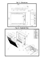
Страница 8: ...Fig 6 Exploded View Fig 5 Dimensions ...