EU and EW Series Valves
Instruction Manual
August 2010
10
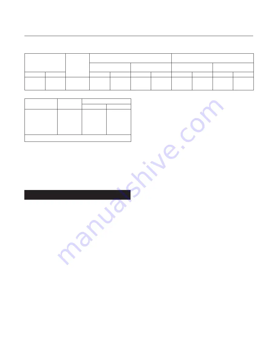
Table 3. Packing Flange Nut Torque for Packing Without a Spring
VALVE
STEM
DIAMETER
PRESSURE
RATING
GRAPHITE-TYPE
PACKING
PTFE-TYPE
PACKING
Minimum
Torque
Maximum
Torque
Minimum
Torque
Maximum
Torque
mm
Inch
N
S
m
Lbf
S
ft
N
S
m
Lbf
S
ft
N
S
m
Lbf
S
ft
N
S
m
Lbf
S
ft
31.8
1-1/4
CL150 & 300
CL600
CL900
33
45
56
24.3
33.2
41.3
49
67
83
36.1
49.4
61.2
16
21
27
11.8
15.5
19.9
25
33
41
18.4
24.3
30.2
Table 4. Body-to-Bonnet Bolt Torque
VALVE SIZE,
NPS
PRESSURE
RATING
BOLTING TORQUE
(1)
N
S
m
Lbf
S
ft
12, 16 x 12
16
16
20 x 16, 24 x 16
20 x 16
20, 24 x 20
CL150 - 600
CL150 - 600
CL900
CL150 - 600
CL900
CL150 - 600
1750
2800
1250
2800
1250
4240
1290
2070
920
2070
920
3130
1. For B7, B7M, B16, and 660 bolting materials. For other materials, contact your
Emerson Process Management sales office for torque values.
8. Install screws or bolts into the tapped holes in the
top of the cage assembly (key 3), and carefully lift it
out of the valve body. Remove the cage gasket
(key 11).
9. If further trim maintenance is required, refer to the
Trim Maintenance section.
CAUTION
To prevent damage to the valve cavity,
packing box wall, and packing
surfaces, observe the instructions in
the next three steps.
10. Cover the opening in the valve body to protect
the gasket surface and prevent foreign material from
getting into the valve cavity.
11. Remove the packing flange nuts, packing
flange, upper wiper, and packing follower
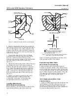
(keys 5, 3, 12, and 13, figure 5). Carefully push out
all the remaining packing parts from the valve side of
the bonnet using a rounded rod or other tool that will
not scratch the packing box wall. Clean the packing
box and the metal packing parts.
12. Inspect the valve stem threads and packing box
surfaces for any sharp edges that might cut the
packing. Scratches or burrs could cause packing box
leakage or damage to the new packing. If the
surface condition cannot be improved by light
sanding or honing with a tool similar to an
automotive brake-cylinder hone, replace the
damaged parts.
13. Remove the covering protecting the valve
cavity, and install a new cage gasket (key 11,
figure 7 and 8), making sure the gasket seating
surfaces are clean and smooth.
14. Re-install the trim parts by following the Trim
Replacement section. Install a new bonnet gasket
(key 10, figure 7 and 8).
Note
Proper performance of the tightening
procedures in step 15 compresses the
bonnet and cage gaskets (keys 10 and
11, figure 7 and 8) enough to seal the
body-to-bonnet joint.
The bolting procedures in step 15
include--but are not limited
to--ensuring that bolting threads are
clean and evenly tightening the hex
nuts onto the studs in a crisscross
pattern. Because of the boltup
characteristics of the gaskets,
tightening one nut may loosen an
adjacent nut. Repeat the crisscross
tightening pattern several times until
each nut is tight and the
body-to-bonnet seal is made.
15. Lubricate the stud bolts (key 15, figure 7 and 8)
with anti-seize lubricant, slide the bonnet over the
stem and onto the bolts, and secure with the stud
bolt nuts (key 16, figure 7 and 8), using accepted
bolting procedures during tightening so that the
body-to-bonnet joint will withstand test pressures
and application service conditions. Refer to table 4
for bolting torque guidelines.
16. Install new packing and the metal packing box
parts according to the appropriate arrangement in
figure 4. Place a smooth-edged pipe over the valve
stem, and gently tap each soft packing part into the
packing box one piece at a time, being sure that air
is not trapped between adjacent soft parts.
17. Slide the packing follower, upper wiper, and
packing flange (keys 13, 12, and 3, figure 5) into
position. Lubricate the packing flange studs (key 4,
figure 5) and the faces of the packing flange nuts
(key 5, figure 5). Replace the packing flange nuts.


