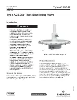


Type ACE95JR
7
Disassembly and Assembly
CAUTIOn
Before removing the valve from the line,
ensure that it is isolated from the gas
supply pressure and that all pressure
has been released from the valve. (The
drain on the inlet filter is convenient
to bleed off gas.) All tank connections
must be closed or sealed in accordance
with your plant’s operating and safety
procedures. If installed, electrical
connections to the explosion proof
switch must be deactivated before
opening the enclosure or disconnecting
the wiring (in accordance with codes
and safety practices).
It is recommended that all seals and diaphragms be
replaced as a matter of good practice whenever a
valve is disassembled and re-assembled. Parts kits
are available through your local Sales Office.
note
When ordering parts, have your model
number, serial number and control
pressure range. Valve information is on
the nameplate (attached to the upper
actuator case).
When performing disassembly or re-assembly
operations, refer to Figure 6 for key numbers (unless
otherwise directed).
Disassembly
!
WArnIng
To avoid personal injury resulting from
sudden release of pressure, isolate the
valve from all pressure and cautiously
release trapped pressure from the valve
before attempting disassembly.
Actuator/Diaphragm Disassembly
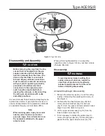
1. Remove the actuator cap (key 1) and the spring
load by unthreading the adjusting screw (key 2).
See Figure 4.
2.
Unthread the hex-head screws (key 29) and
remove the lock washers (key 28) and nuts
(key 31) from the upper and lower actuator cases
(keys 33 and 30). Refer to Figure 6.
3. Lift the upper actuator case (key 33) from the
lower actuator case (key 30).
4. If it is necessary to replace the gasket (key 9),
remove the spring case (key 7) and spring case
gasket from the upper actuator case (key 33).
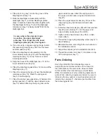
Figure 5.
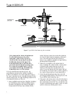
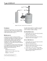
Cage Assembly
POPPET (STEM)
(KEy 42)
rOllIng DIAPHrAgM
(KEy 38)
W8162
CrOSS-DrIllED HOlE
O-rIng
(KEy 39)
PISTOn
(KEy 37)
W8161
CAgE
(KEy 52)