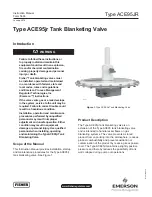


Type ACE95JR
2
Specifications
This section lists the specifications and ratings for the Type ACE95jr tank blanketing valve. Factory specifications
are stamped on a nameplate fastened to the actuator of the valve.
Sizes and End Connection Styles
1/2 NPT
1 x 1/2 NPT
1 NPT
NPS 1/2 / DN 15, CL150 RF
NPS 1 / DN 25, CL150 RF
NPS 1 x 1/2 / DN 25 x 15, CL150 RF
NPS 1 / DN 25, Sanitary Flange
Maximum Operating Inlet Pressure
(1)
200 psig / 13.8 bar
Maximum Emergency Outlet (Casing) Pressure
(1)
20 psig / 1.4 bar
Maximum Operating Control Pressure
(1)
1.5 psig / 0.10 bar
Control Pressure ranges
(1)
-5 in. w.c. to 1.5 psig /
-12 mbar to 0.10 bar in six ranges
See Table 1
Pressure registration
External
Main Valve Flow Characteristic
Linear
Flow Coefficients for Relief Valve Sizing
(110% of rated C
v
)
C
v
0.2 use C
v
0.22
C
v
0.4 use C
v
0.44
IEC Sizing Coefficients
X
t
:
0.655
F
d
:
0.86
F
l
:
0.89
Temperature Capabilities
(1)
nitrile (nBr):
-20 to 180°F / -29 to 82°C
Fluorocarbon (FKM):
0 to 212°F / -18 to 100°C
Ethylenepropylene (EPDM-FDA):
-20 to 212°F / -29 to 100°C
Perfluoroelastomer (FFKM):
-20 to 212°F / -29 to 100°C
Approximate Weight (with all accessories)
30 lbs / 14 kg
Table 1.
Control Pressure Ranges
COnTrOl PrESSUrE rAngE
SPrIng rAngE
SPrIng MATErIAl
SPrIng FrEE lEngTH
SPrIng WIrE DIAMETEr
In. w.c.
mbar
In.
mm
In.
mm
-5 to -0.5
-12 to -1
GC220701X22
Stainless Steel
2.75
0.88
69.9
22.4
(1)
0.080
0.085
2.03
2.16
(1)
-1 to 1
-2 to 2
GC220701X22
Stainless Steel
2.75
1.60
69.9
40.6
(1)
0.080
0.065
2.03
1.65
(1)
0.5 to 5
4 to 10
8 to 15
0.5 to 1.5 psig
1 to 12
10 to 25
20 to 37
0.03 to 0.10 bar
GC220701X22
GC220702X22
GC220703X22
GC220708X22
Stainless Steel
Stainless Steel
Stainless Steel
Stainless Steel
2.75
2.00
2.00
2.75
69.6
50.8
50.8
69.6
0.080
0.112
0.125
0.225
2.03
2.85
3.18
5.72
1. The second spring is located under the diaphragm assembly.
1. The pressure/temperature limits in this Instruction Manual and any applicable standard or code limitation should not be exceeded.