


Type ACE95JR
5
Piping Considerations
note
Piping lengths are best when they are
kept short with a minimum number of
elbows and fittings.
Inlet Piping
CAUTIOn
Undersized piping may inadequately
deliver blanketing gas at the
specified inlet pressure under full
flow conditions. This may result in
unacceptable performance under high
demand conditions.
The blanketing gas supply line should be equipped with
a Number 100 mesh strainer to remove dirt and pipe
scale. Inlet piping must be sized to adequately deliver
blanketing gas at the specified inlet pressure under full
flow conditions.
Outlet Piping
CAUTIOn
Unnecessarily long or restricted outlet
piping may result in poor setpoint control.
Valve outlet is piped into the tank vapor space. Outlet
piping must be full size and self-draining to the tank.
The valve should be situated above and as close as
possible to the tank vapor space for best performance.
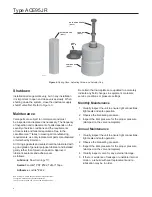
Sensing Line
The sensing line should be 1/2 in. / 13 mm tubing or
pipe, must slope toward the tank and should not contain
low points (or traps) that could catch liquid. The sensing
line must enter the tank above the liquid level at a point
that senses the vapor space pressure and is free from
turbulence associated with tank nozzles or vents.
note
Best control is obtained when both
connections to the tank are separate.
If the tank has only one available
nozzle, contact Emerson™. for alternate
methods of installation. A single array
manifold is available for such situations.
Gauges and Shutoff Valves
Inlet gas shutoff valves are desirable for servicing.
If this Type ACE95jr tank blanketing valve was not
ordered with an inlet pressure gauge, it is advisable to
install a gauge between the inlet shutoff valve and the
blanketing valve.
note
Safety considerations may dictate full
port shutoff valves between the tank and
blanketing valve and at the valve inlet.
Startup, Adjustment and Shutdown
note
Tank vents and safety relief valves must
be in place and operating.
Startup
CAUTIOn
Always open the outlet valve before
the inlet valve. Operation in the reverse
order could result in inlet pressure being
applied to the actuator casing, potentially
damaging it.
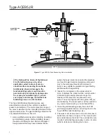
1.
Open shutoff valves between the blanketing valve
and the tank (both sensing and outlet). See Figure 3.
2.
Slowly open the supply line shutoff valve (to the
blanketing valve) and leave it fully open.
3. Monitor the tank vapor space pressure.
Adjustment
The setpoint of this unit is factory set. Adjustments
should be made in small increments while the unit is
supplying gas to the tank. To change the setpoint:
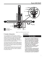
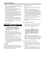
1. Remove the actuator cap (key 1) from the top of
the spring case (key 7). See Figure 4.
2. Loosen the lock nut (key 3) and turn the adjusting
screw (key 2) clockwise to raise the setpoint.
(Turning the screw counter-clockwise lowers
the setpoint.)
3.
Observe the effects of the change.
4. When the adjustment is complete, tighten the lock
nut (key 3) and replace the actuator cap (key 1).