background image

Type 4000

6

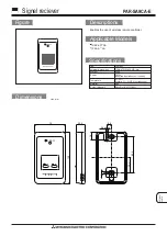
Figure 8. Front Cover and Indicator Cover

FRONT COVER

INDICATOR
COVER O-RING

IDENTIFICATION
COVER

INDICATOR
COVER

FRONT
COVER
O-RING

NOTCH

FRONT COVER SHOWN WITH O-RING LOOPED
OVER NOTCHES TO PERMIT DRAINING

A7196 / IL

Instrument Connection

Connect the control device 3 to 15 psig (0.2 to 1.0 bar)
output to port on the adapter housing. If a gauge to
monitor the input signal is desired, remove the plug
from gauge port I

p

 and install an appropriate pressure

gauge.

Output Gauge

If an output gauge is desired, remove the plug from
gauge port C and install an appropriate pressure
gauge.

Vent

WARNING

If a flammable, toxic, or reactive gas is
to be used as the supply pressure me-
dium, personal injury or property dam-
age could result from fire or explosion
of accumulated gas or from contact with
toxic, or reactive gas. The positioner/ac-
tuator assembly does not form a gas-
tight seal, and when the assembly is in
an enclosed area, adequate ventilation
and necessary safety measures should
be used.

There is no pipe fitting for remote venting. The posi-
tioner exhaust is under the actuator cover.

Operating Information

Front Cover and Indicator Cover

The positioner front cover is shown in figure 8. It is
secured to the unit with four captive screws and
sealed with an O-ring. The front cover O-ring can be
looped over notches in the front cover to allow for
drainage. There are eight locations on the front cover
where the O-ring can be looped. This unique sealing
system allows for complete sealing or draining of the
units by changing the position of the front cover O-
ring.

The indicator cover is O-ring sealed and secured by a
bayonet coupling. The indicator cover also secures the
identification cover to the front cover.

To remove the indicator cover, turn it slightly counter-
clockwise until it loosens. The identification cover and
indicator cover O-ring are now removable. When
installing the indicator cover and identification cover,
make sure that the indicator cover O-ring is properly
engaged.

Two identification covers are available: one for actua-
tor travels of 3/4-inch (19.1 mm) or less, and one for

Содержание 4000

Страница 1: ... Replacing the Positioner 10 Parts Ordering 11 Parts List 11 Introduction Scope of Manual This instruction manual provides installation operat ing calibration maintenance and parts ordering in formation for the Type 4000 pneumatic valve Figure 1 Type 4000 Positioner Installed on System 9000 Actuator W7371 IL positioner Refer to separate instruction manuals for information on the actuator control v...

Страница 2: ...tic valve positioner is designed for use with System 9000 actuators The positioner mounts on the actuator and provides the desired valve plug position for a specific input signal The Type 4000 accepts a pneumatic input signal The positioner comes standard with gauge ports and an O ring sealed housing The housing utilizes a unique O ring seal that can be adjusted to a sealed or drained position Eas...

Страница 3: ...ey 1B from the positioner spindle by removing the flathead screw that holds the lever to the spindle Figure 3 Assembling the Type 4000 Positioner to the Adapter Housing ADAPTER HOUSING KEY 1C POSITIONER KEY 1A MOUNTING SCREWS W7369 IL Note Mounting the positioner key 1A may be easier with the adapter housing key 1C removed from the actuator 2 To remove the adapter housing key 1C from the actuator ...

Страница 4: ... USE THESE HOLES FOR SIZE 20 ACTUATOR USE THESE HOLES FOR SIZE 50 AND 80 ACTUATORS W7048 IL 9 Refer to figure 6 Install the feedback bracket key 108 to the top of the power module with two cap screws key 105 and washers key 122 10 If necessary make minor adjustments of the feed back lever arm assembly pin to ensure that the feed back bracket and feedback lever arm assembly do not pinch bind or ben...

Страница 5: ...ticles 40 microns in diameter should suffice for most applications Use of suitable filtration equipment and the es tablishment of a maintenance cycle to monitor its operation is recommended The supply medium must be clean dry air or noncor rosive gas that meets the requirements of ISA Stan dard S7 3 1975 R1981 The supply pressure should not exceed the following limits For the actuator and position...

Страница 6: ...on and necessary safety measures should be used There is no pipe fitting for remote venting The posi tioner exhaust is under the actuator cover Operating Information Front Cover and Indicator Cover The positioner front cover is shown in figure 8 It is secured to the unit with four captive screws and sealed with an O ring The front cover O ring can be looped over notches in the front cover to allow...

Страница 7: ...ure the cam make sure the screw is backed out from the locking nut Tighten the locking nut finger tight then tighten the screw Install and adjust the indi cator and reinstall the cover Indicator Adjustment To adjust the indicator remove the front cover and pull the indicator upwards until it comes off the Allen screw Before installing the indicator make sure that the Allen screw is tight Press the...

Страница 8: ...re 11 Principle of Operation 1 2 3 4 5 6 7 8 A7199 IL If the actuator travel recorded in step 5 is short of the desired travel at 100 input signal rotate the span adjustment down to increase span Tighten the locking screw If the travel recorded in step 5 reaches the de sired travel before the input signal reaches the 100 value rotate the span adjustment up to decrease span Tighten the locking scre...

Страница 9: ...loading pressure and relieve any actuator spring precompres sion Use lock out procedures to be sure that the above measures stay in effect while you work on the equipment Other than the pilot valve repair of the positioner is by replacement To replace the positioner see the Posi tioner Removal and Positioner Replacement sections To replace the pilot valve see Replacing the Pilot Valve On units wit...

Страница 10: ...1 Shut off supply pressure and process lines to the positioner 2 Remove the defective gauge from the adapter housing 3 Coat the threads of the replacement gauge with a sealant Zink plate No 770 or equivalent Figure 13 Diaphragm DIAPHRAGM COVER SCREWS SCREW WASHERS DIAPHRAGM A7201 IL 4 Screw the replacement gauge into the adapter housing gauge connection 5 Apply supply pressure to the positioner Us...

Страница 11: ...ation Cover For 3 4 19 1 mm travel or less P5FV30R 18B2836X012 For greater than 3 4 19 1 mm travel P5FV60R 18B2835X012 3 Instrument Gauge Triple Scale 0 30 psi 2 bar 0 2 MPa 11B4036X012 4 Supply Gauge Triple Scale 0 160 psi 11 bar 1 1 MPa 11B4036X032 Key Description Part Number 5 Output Gauge Triple Scale 0 160 psi 11 bar 1 1 MPa 11B4036X032 Test Connections use when gauges or pipe plugs are not s...

Страница 12: ... 05424 Brazil Singapore 128461 Printed in U S A Fisher Controls International Inc 1998 1999 All Rights Reserved Fisher Fisher Rosemount and Managing The Process Better are marks owned by Fisher Controls International Inc or Fisher Rosemount Systems Inc All other marks are the property of their respective owners ...

Отзывы: