background image

Type 4000

10

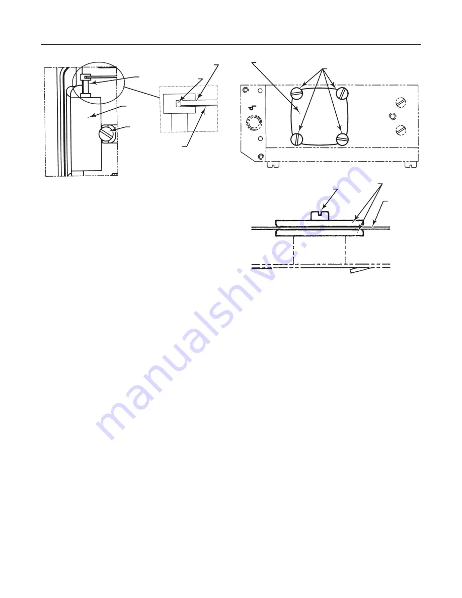
Figure 12. Pilot Valve Assembly

SCREW

PILOT 
VALVE
ASSEMBLY

SPOOL

SPOOL GROVE

BALANCE ARM

LEAF SPRING

A7200 / IL

5.  Check the O-rings, then secure and install the pilot
valve assembly to the positioner housing and secure it
with the screw. Make sure that the leaf spring on the
balance arm is properly fitted in the spool groove.

6.  Check again to insure smooth operation of the as-
sembly.

Replacing the Diaphragm

Refer to figure 13.

1.  Loosen the four screws and remove the diaphragm
cover.

2.  Loosen the screw that secures the diaphragm. Re-
move the diaphragm and washers.

When installing the diaphragm make sure to place one
washer on each side of the diaphragm. Make sure that
the raised circle on the washers is facing the dia-
phragm.

3.  Install the screw and tighten.

4.  Check the O-ring on the diaphragm cover, then
install and secure the cover with the four screws.

Replacing Gauges

1.  Shut off supply pressure and process lines to the
positioner.

2.  Remove the defective gauge from the adapter
housing.

3.  Coat the threads of the replacement gauge with a
sealant (Zink plate No. 770 or equivalent).

Figure 13. Diaphragm

DIAPHRAGM COVER

SCREWS

SCREW

WASHERS

DIAPHRAGM

A7201 / IL

4.  Screw the replacement gauge into the adapter
housing gauge connection.

5.  Apply supply pressure to the positioner. Using a
soap solution, check around the ports and connections
for leaks.

Removing the Positioner

1.  Shut off supply pressure and process lines to the
positioner.

2.  Remove the actuator cover.

3.  Remove the flathead screw that secures the feed-
back lever to the positioner spindle. Remove the feed-
back lever from the spindle.

4.  Refer to figure 3. Remove the four mounting
screws from the bottom of the adapter housing.

5.  Lift the positioner off the adapter housing.

Replacing the Positioner

1.  Replace the positioner on the actuator by perform-
ing the mounting and connection procedures in the
“Installation” section.

2.  Calibrate the positioner by performing the proce-
dures in the “Calibration” section.

Содержание 4000

Страница 1: ... Replacing the Positioner 10 Parts Ordering 11 Parts List 11 Introduction Scope of Manual This instruction manual provides installation operat ing calibration maintenance and parts ordering in formation for the Type 4000 pneumatic valve Figure 1 Type 4000 Positioner Installed on System 9000 Actuator W7371 IL positioner Refer to separate instruction manuals for information on the actuator control v...

Страница 2: ...tic valve positioner is designed for use with System 9000 actuators The positioner mounts on the actuator and provides the desired valve plug position for a specific input signal The Type 4000 accepts a pneumatic input signal The positioner comes standard with gauge ports and an O ring sealed housing The housing utilizes a unique O ring seal that can be adjusted to a sealed or drained position Eas...

Страница 3: ...ey 1B from the positioner spindle by removing the flathead screw that holds the lever to the spindle Figure 3 Assembling the Type 4000 Positioner to the Adapter Housing ADAPTER HOUSING KEY 1C POSITIONER KEY 1A MOUNTING SCREWS W7369 IL Note Mounting the positioner key 1A may be easier with the adapter housing key 1C removed from the actuator 2 To remove the adapter housing key 1C from the actuator ...

Страница 4: ... USE THESE HOLES FOR SIZE 20 ACTUATOR USE THESE HOLES FOR SIZE 50 AND 80 ACTUATORS W7048 IL 9 Refer to figure 6 Install the feedback bracket key 108 to the top of the power module with two cap screws key 105 and washers key 122 10 If necessary make minor adjustments of the feed back lever arm assembly pin to ensure that the feed back bracket and feedback lever arm assembly do not pinch bind or ben...

Страница 5: ...ticles 40 microns in diameter should suffice for most applications Use of suitable filtration equipment and the es tablishment of a maintenance cycle to monitor its operation is recommended The supply medium must be clean dry air or noncor rosive gas that meets the requirements of ISA Stan dard S7 3 1975 R1981 The supply pressure should not exceed the following limits For the actuator and position...

Страница 6: ...on and necessary safety measures should be used There is no pipe fitting for remote venting The posi tioner exhaust is under the actuator cover Operating Information Front Cover and Indicator Cover The positioner front cover is shown in figure 8 It is secured to the unit with four captive screws and sealed with an O ring The front cover O ring can be looped over notches in the front cover to allow...

Страница 7: ...ure the cam make sure the screw is backed out from the locking nut Tighten the locking nut finger tight then tighten the screw Install and adjust the indi cator and reinstall the cover Indicator Adjustment To adjust the indicator remove the front cover and pull the indicator upwards until it comes off the Allen screw Before installing the indicator make sure that the Allen screw is tight Press the...

Страница 8: ...re 11 Principle of Operation 1 2 3 4 5 6 7 8 A7199 IL If the actuator travel recorded in step 5 is short of the desired travel at 100 input signal rotate the span adjustment down to increase span Tighten the locking screw If the travel recorded in step 5 reaches the de sired travel before the input signal reaches the 100 value rotate the span adjustment up to decrease span Tighten the locking scre...

Страница 9: ...loading pressure and relieve any actuator spring precompres sion Use lock out procedures to be sure that the above measures stay in effect while you work on the equipment Other than the pilot valve repair of the positioner is by replacement To replace the positioner see the Posi tioner Removal and Positioner Replacement sections To replace the pilot valve see Replacing the Pilot Valve On units wit...

Страница 10: ...1 Shut off supply pressure and process lines to the positioner 2 Remove the defective gauge from the adapter housing 3 Coat the threads of the replacement gauge with a sealant Zink plate No 770 or equivalent Figure 13 Diaphragm DIAPHRAGM COVER SCREWS SCREW WASHERS DIAPHRAGM A7201 IL 4 Screw the replacement gauge into the adapter housing gauge connection 5 Apply supply pressure to the positioner Us...

Страница 11: ...ation Cover For 3 4 19 1 mm travel or less P5FV30R 18B2836X012 For greater than 3 4 19 1 mm travel P5FV60R 18B2835X012 3 Instrument Gauge Triple Scale 0 30 psi 2 bar 0 2 MPa 11B4036X012 4 Supply Gauge Triple Scale 0 160 psi 11 bar 1 1 MPa 11B4036X032 Key Description Part Number 5 Output Gauge Triple Scale 0 160 psi 11 bar 1 1 MPa 11B4036X032 Test Connections use when gauges or pipe plugs are not s...

Страница 12: ... 05424 Brazil Singapore 128461 Printed in U S A Fisher Controls International Inc 1998 1999 All Rights Reserved Fisher Fisher Rosemount and Managing The Process Better are marks owned by Fisher Controls International Inc or Fisher Rosemount Systems Inc All other marks are the property of their respective owners ...

Отзывы: