FISCHER DS 11 Скачать руководство пользователя страница 4


4 | 16 Page 


• 

The electrical connection of the device shall be 
performed according to relevant VDE  and  local 
electricity board regulations. 

• 

Disconnect  the  system  from  the  mains  before 
connecting the device. 

• 

Add a fuse adapted to the energy requirements. 
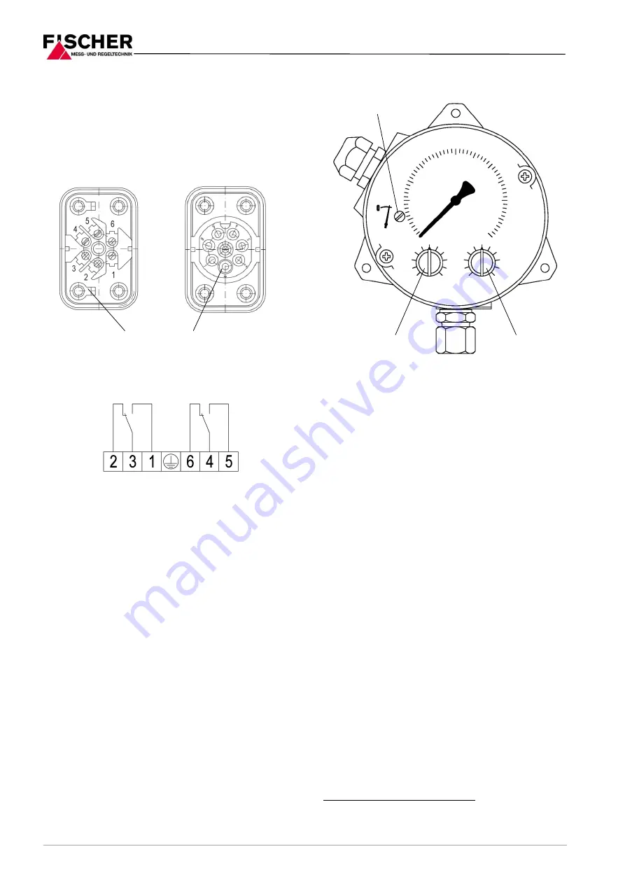
4.2.1 

Cable socket and plug connection 


Cable socket 

Plug connection 


4.2.2 

Numbered cables 

For  models  with  numbered  cables,  the  cable  num-
bers  correspond  with  the  presented  terminal  num-
bers. 


Commissioning 

All electrical supply, operating and measuring lines, 
and the pressure connections must have been cor-
rectly  installed  before  commissioning.  All  supply 
lines are  arranged so  that  there  are no mechanical 
forces acting on the device. 

Check  that  the  pressure  connections  do  not  leak 
before commissioning. 

5.1 

Control Elements 


5.2 

Zero point correction 


Depressurize the measuring chamber. 


Remove the hood 


Set the measurement value pointer to the zero-
point  scale  using  the  zero  point  correction 
screw. 


Re-mount the hood. 

5.3 

Switch point setting 


Remove the plug in the hood. 


The  required  switch  points  can  be  set  guide 
value  scales  according  to  the  markings  by  us-
ing a screwdriver. The achievable setting accu-
racy is ± 5 %. 

1


Replace the plug after completing the settings. 

5.4 

Function test 

Remove both plugs in the hood for testing.  

If  the  unit  has  two  micro-switches,  the  stated  test 
steps must be carried out for both switches. 

After  the  test,  the  switch  points  need  to  be  reset 
acc. to 5.3. 

5.4.1 

Checking the switch points when the 
system is depressurized.  

No  measurement  is  shown  and  the  measurement 
display points to zero. 

Turn the switch point setting button toward the zero-
point until the micro-switch is activated. 


1

More accurate settings can be made either in the factory or on 

site using suitable aids (test manometer, ohm meter etc.) 

Ground connection 

Zero-point correction screw 

Switch point setting 

switch 1 

Switch point setting 

switch 2 

Switch 1 

Switch 2 

Содержание DS 11

Страница 1: ...ar with the in stallation commissioning and operation of this product Specialized personnel are persons who can assess the work they have been assigned and recognize potential dangers by virtue of their specialized train ing their skills and experience and their knowledge of the pertinent standards 1 3 Risks due to Non Observance of Safe ty Instructions Non observance of these safety instructions ...

Страница 2: ...toring filters and pumps Pressure chamber and measuring diaphragms are available in various materials This allows the devices to be adapted to the various requirements 3 Product and functional description 3 1 Function diagram Item Description 1 Pressure chamber 2 Motion train 3 Tappet 4 Micro switch 5 Switch point setting 6 Measuring diaphragm 7 Measuring springs 3 2 Design and mode of operation A...

Страница 3: ...r pressure to the side of the device When measuring the pressure only the connection is used the connection is used to measure under pressure The pressure sensing lines need to be kept as short as possible and installed without sharp bends to avoid interfering delay times The pressure sensing lines must be installed on a gradient so that no air pockets e g for liquid meas urements or water pockets...

Страница 4: ... Set the measurement value pointer to the zero point scale using the zero point correction screw Re mount the hood 5 3 Switch point setting Remove the plug in the hood The required switch points can be set guide value scales according to the markings by us ing a screwdriver The achievable setting accu racy is 5 1 Replace the plug after completing the settings 5 4 Function test Remove both plugs in...

Страница 5: ...tected against impacts It should be transported in the original packaging or a suitable transport container 8 Service All defective or faulty devices should be sent direct ly to our repair department Please coordinate all shipments with our sales department Warning Process media residues in and on dismantled devices can be a hazard to people animals and the environment Take adequate preventive mea...

Страница 6: ...measuring range Switch hysteresis approx 2 5 of the upper range value Load data contact AC DC Umax 250V 30V Imax 5A 0 4A Pmax 250 VA 10 W Ports Process connection Inner thread G 1 4 Connecting shank G DIN EN 837 Cutting ring connections for 6 8 10 mm brass steel galvanized or stainless steel electr connection Fixed wire numbered cables Cable connection socket 7 pole plug connection Materials Press...

Страница 7: ... Process connection variants M20x1 5 Cable screw connection Cable connection socket or 7 pin plug connection SW19 Connection G inner thread Connection spigot G according to DIN EN 837 DZ 13 14 Four spindle equalization and shut off valve Mounting the control panel opened opened Measuring device Venting Function diagram DZ 13 14 Venting n a for DZ13 Cutting ring screw connection Control panel cut o...

Страница 8: ...read 1 4 18 NPT EXT Chrome Nickel Steel 1 4 Cutting ring screw connection made of steel for 6 mm pipe 2 0 Cutting ring screw connection made of steel for 8 mm pipe 2 1 Cutting ring screw connection made of steel for 10 mm pipe 2 2 Cutting ring screw connection made of 1 4571 for 6 mm pipe 2 4 Cutting ring screw connection made of 1 4571 for 8 mm pipe 2 5 Cutting ring screw connection made of 1 457...

Страница 9: ...d or taken out of operation for repairs or tests to disconnect differential pressure devices within the affected systems from the mains supply The shutoff devices can therefore also be used for function tests on site In contrast to DZ13 the DZ14 also has a venting valve to vent the conected pipe system The shutoff and venting valves are designed for the rated pressure level PN40 The housing can be...

Страница 10: ...10 16 Page 14 Manufacturer s Declarations and Certificates 14 1 EC Declaration of conformity ...

Страница 11: ...11 16 Page 14 2 Certificate functional security SIL2 ...

Страница 12: ...12 16 Page ...

Страница 13: ...13 16 Page 14 3 GL approval ...

Страница 14: ...14 16 Page ...

Страница 15: ...15 16 Page ...

Страница 16: ...ithout notice Changements techniques sous réserve Fischer Mess und Regeltechnik GmbH Bielefelder Str 37a D 32107 Bad Salzuflen Tel 49 5222 9740 Fax 49 5222 7170 eMail info fischermesstechnik de www fischermesstechnik de 14 4 EAC Declaration of conformity ...

Отзывы: