FISCHER DS 11 Скачать руководство пользователя страница 1


  d e v e l o p i n g  

  s o l u t i o n s  

*0

9

0

0

5

1

0

4

B

A

_

E

N_DS

1

1

 Rev.

E


1

1

/1

9


*09

005104

Contents 

1


Safety guidelines


2


Application purpose


3


Product and functional description


4


Installation and assembly


5


Commissioning


6


Maintenance and Repeat Tests


7


Transport


8


Service


9


Accessories


10


Waste Disposal


11


Technical data


12


Dimensional drawings


13


Order Codes


14


Manufacturer's Declarations and Certificates


Safety guidelines 

1.1 

General 

This  operating  manual  contains  instruc-
tions  fundamental  to  the  installation, 
operation  and  maintenance  of  the  de-
vice  that  must  be  observed  uncondi-

tionally.  It  must  be  read  by  the  fitter,  the  operator 
and  the  responsible  technical  personnel  before  in-
stallation and commissioning of the device.  

This  operating  manual  is  an  integral  part  of  the 
product and therefore needs to be kept close to the 
instrument  in  a  place  that  is  accessible  at  all  times 
to the responsible personnel. 

The  following  sections,  in  particular  instructions 
about  the  assembly,  commissioning  and  mainte-
nance, 

contain 

important 

information, 

non-

observance  of  which  could  pose  a  threat  to  hu-
mans, animals, the environment and property. 

1.2 

Personnel Qualification 

The  device  may  only  be  installed  and  commis-
sioned by specialized personnel familiar with the in-
stallation,  commissioning  and  operation  of  this 
product. 

Specialized personnel are persons who can assess 
the  work  they  have  been  assigned  and  recognize 
potential dangers by virtue of their specialized train-
ing, their skills and experience and their knowledge 
of the pertinent standards. 

1.3 

Risks due to Non-Observance of Safe-
ty Instructions 

Non-observance of these safety instructions, the in-
tended use of the device or the limit values given in 
the  technical  specifications  can  be  hazardous  or 
cause  harm  to  persons,  the  environment  or  the 
plant itself.  

The  supplier  of  the  equipment  will  not  be  liable  for 
damage claims if this should happen. 

1.4 

Safety Instructions for the Operating 
Company and the Operator 

The  safety  instructions  governing  correct  operation 
of  the instrument  must  be  observed.  The  operating 
company must make them available to the  installa-
tion,  maintenance,  inspection  and  operating  per-
sonnel.  

Dangers arising from electrical components, energy 
discharged  by  the  medium,  escaping  medium  and 
incorrect installation of the device must be eliminat-
ed.  See  the  information  in  the  applicable  national 
and international regulations. 

1.5 

Unauthorized Modification 

Modifications of or other technical alterations to the 
instrument  by  the  customer  are  not  permitted. This 
also applies to replacement parts. Only 
the manufacturer is authorized to make 
any modifications or changes. 
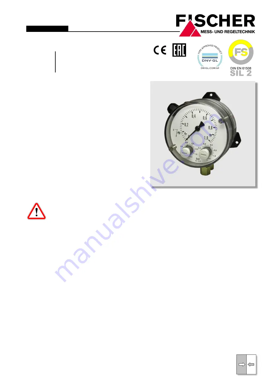
 

User Manual  


DS11 

Differential pressure switch 


Содержание DS 11

Страница 1: ...ar with the in stallation commissioning and operation of this product Specialized personnel are persons who can assess the work they have been assigned and recognize potential dangers by virtue of their specialized train ing their skills and experience and their knowledge of the pertinent standards 1 3 Risks due to Non Observance of Safe ty Instructions Non observance of these safety instructions ...

Страница 2: ...toring filters and pumps Pressure chamber and measuring diaphragms are available in various materials This allows the devices to be adapted to the various requirements 3 Product and functional description 3 1 Function diagram Item Description 1 Pressure chamber 2 Motion train 3 Tappet 4 Micro switch 5 Switch point setting 6 Measuring diaphragm 7 Measuring springs 3 2 Design and mode of operation A...

Страница 3: ...r pressure to the side of the device When measuring the pressure only the connection is used the connection is used to measure under pressure The pressure sensing lines need to be kept as short as possible and installed without sharp bends to avoid interfering delay times The pressure sensing lines must be installed on a gradient so that no air pockets e g for liquid meas urements or water pockets...

Страница 4: ... Set the measurement value pointer to the zero point scale using the zero point correction screw Re mount the hood 5 3 Switch point setting Remove the plug in the hood The required switch points can be set guide value scales according to the markings by us ing a screwdriver The achievable setting accu racy is 5 1 Replace the plug after completing the settings 5 4 Function test Remove both plugs in...

Страница 5: ...tected against impacts It should be transported in the original packaging or a suitable transport container 8 Service All defective or faulty devices should be sent direct ly to our repair department Please coordinate all shipments with our sales department Warning Process media residues in and on dismantled devices can be a hazard to people animals and the environment Take adequate preventive mea...

Страница 6: ...measuring range Switch hysteresis approx 2 5 of the upper range value Load data contact AC DC Umax 250V 30V Imax 5A 0 4A Pmax 250 VA 10 W Ports Process connection Inner thread G 1 4 Connecting shank G DIN EN 837 Cutting ring connections for 6 8 10 mm brass steel galvanized or stainless steel electr connection Fixed wire numbered cables Cable connection socket 7 pole plug connection Materials Press...

Страница 7: ... Process connection variants M20x1 5 Cable screw connection Cable connection socket or 7 pin plug connection SW19 Connection G inner thread Connection spigot G according to DIN EN 837 DZ 13 14 Four spindle equalization and shut off valve Mounting the control panel opened opened Measuring device Venting Function diagram DZ 13 14 Venting n a for DZ13 Cutting ring screw connection Control panel cut o...

Страница 8: ...read 1 4 18 NPT EXT Chrome Nickel Steel 1 4 Cutting ring screw connection made of steel for 6 mm pipe 2 0 Cutting ring screw connection made of steel for 8 mm pipe 2 1 Cutting ring screw connection made of steel for 10 mm pipe 2 2 Cutting ring screw connection made of 1 4571 for 6 mm pipe 2 4 Cutting ring screw connection made of 1 4571 for 8 mm pipe 2 5 Cutting ring screw connection made of 1 457...

Страница 9: ...d or taken out of operation for repairs or tests to disconnect differential pressure devices within the affected systems from the mains supply The shutoff devices can therefore also be used for function tests on site In contrast to DZ13 the DZ14 also has a venting valve to vent the conected pipe system The shutoff and venting valves are designed for the rated pressure level PN40 The housing can be...

Страница 10: ...10 16 Page 14 Manufacturer s Declarations and Certificates 14 1 EC Declaration of conformity ...

Страница 11: ...11 16 Page 14 2 Certificate functional security SIL2 ...

Страница 12: ...12 16 Page ...

Страница 13: ...13 16 Page 14 3 GL approval ...

Страница 14: ...14 16 Page ...

Страница 15: ...15 16 Page ...

Страница 16: ...ithout notice Changements techniques sous réserve Fischer Mess und Regeltechnik GmbH Bielefelder Str 37a D 32107 Bad Salzuflen Tel 49 5222 9740 Fax 49 5222 7170 eMail info fischermesstechnik de www fischermesstechnik de 14 4 EAC Declaration of conformity ...

Отзывы: