


2 | 16 Page
1.6
Inadmissible Modes of Operation
The operational safety of this instrument can only
be guaranteed if it is used as intended. The instru-
ment model must be suitable for the medium used
in the system. The limit values given in the technical
data may not be exceeded.
1.7
Safe working practices for mainte-
nance and installation work
The safety instructions given in this operating man-
ual, any nationally applicable regulations on acci-
dent prevention and any of the operating company's
internal work, operating and safety guidelines must
be observed.
The operating company is responsible for ensuring
that all required maintenance, inspection and instal-
lation work is carried out by qualified specialized
personnel.
1.8
Pictogram explanation
WARNING!
… indicates a potentially dangerous
situation, non-observance of which
could endanger persons, animals, the
environment or objects.
INFORMATION!
… highlights important information ef-
ficient and smooth operation.
TIP!
… indicates recommendations that are
not specifically necessary in certain
situations but which could be useful.
2
Application purpose
The DS 11 is a combined display and switching de-
vice for differential pressure, over-pressure and un-
der-pressure. This series is ideally suited for vari-
ous measuring tasks in industrial applications or the
sanitary field.
Typical applications are measuring differential pres-
sure between the supply and return in heating sys-
tems and monitoring filters and pumps. Pressure
chamber and measuring diaphragms are available
in various materials. This allows the devices to be
adapted to the various requirements.
3
Product and functional description
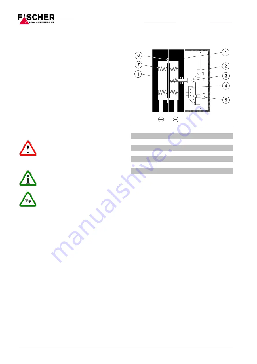
3.1
Function diagram
Item
Description
1
Pressure chamber
2
Motion train
3
Tappet
4
Micro-switch
5
Switch point setting
6
Measuring diaphragm
7
Measuring springs
3.2
Design and mode of operation
A robust and durable membrane measuring instru-
ment is used as a measuring system, which is suit-
able for overpressure and underpressure meas-
urements. The units use the same measuring prin-
ciple for all three measuring applications.
In the rest position, the spring forces on both sides
of the membrane are balanced out. Due to the
pressure or underpressure to be measured, a sin-
gle-sided force is created on the membrane which
shifts the membrane system against the measure-
ment range springs up to equalization of the spring
forces. In case of overload, the membrane supports
against the metallic support surfaces.
A centrally positioned tappet transfers the move-
ment of the membrane system on the motion train
and operating elements of the micro-switches.
4
Installation and assembly
The standard device is designed for wall mounting.
The device can be mounted to even walls using the
assembly foot that is cast to the middle of the de-
vice. It is also possible to fit the device in switch
cabinets using the switch panel installation kit
DZ11.
It is calibrated ex-works for vertical installation; this
is the only allowed installation position.
To ensure safety during installation and mainte-
nance, we recommend installing a suitable shut-off
Содержание DS 11
Страница 10: ...10 16 Page 14 Manufacturer s Declarations and Certificates 14 1 EC Declaration of conformity ...
Страница 11: ...11 16 Page 14 2 Certificate functional security SIL2 ...
Страница 12: ...12 16 Page ...
Страница 13: ...13 16 Page 14 3 GL approval ...
Страница 14: ...14 16 Page ...
Страница 15: ...15 16 Page ...