4150K and 4160K Series
23
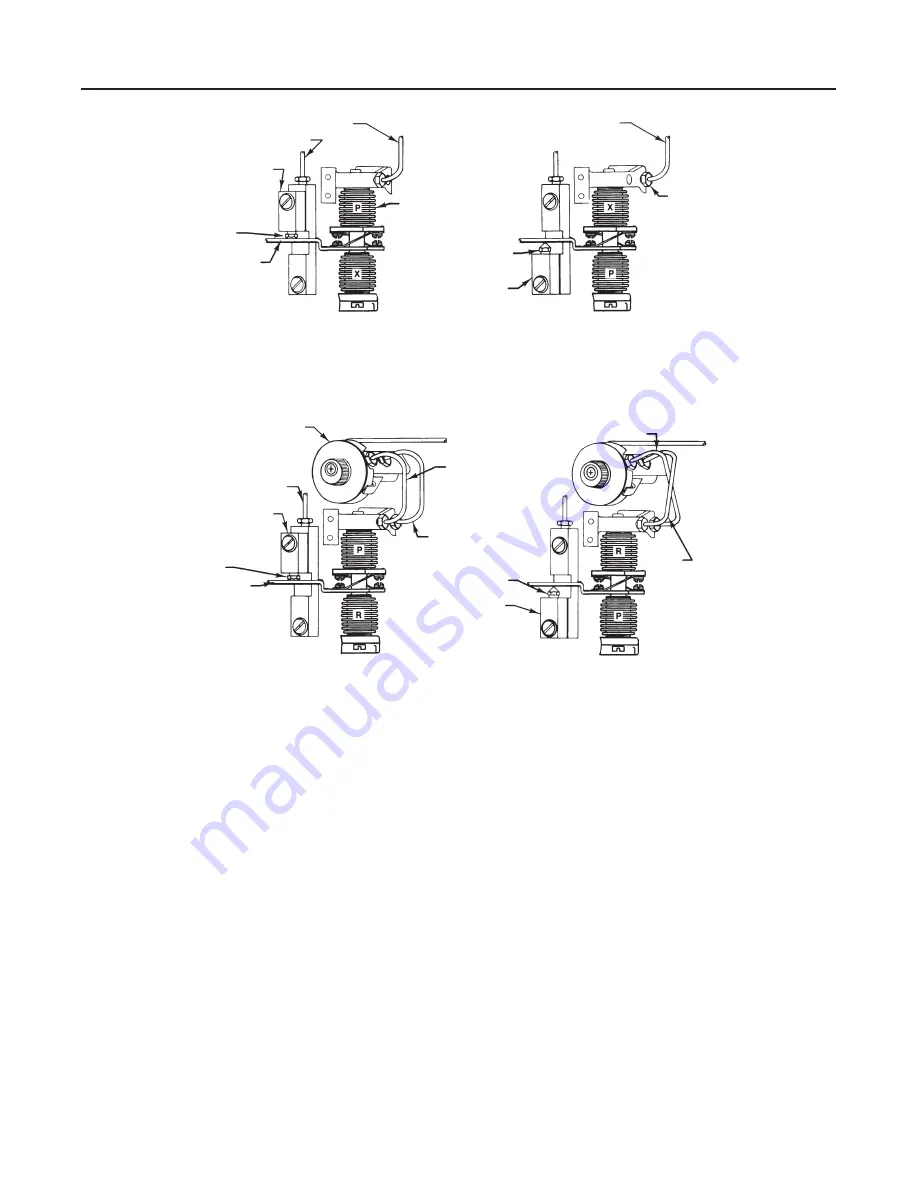
Figure 16. Direct/Reverse Acting Tubing Connections
PROPORTIONAL
TUBING (KEY 104)
RELAY TUBING (KEY 103)
REVERSING
BLOCK (KEY 59)
DIRECT
ACTING
POSITION
BEAM (KEY 44)
BELLOWS
(KEY 52)
REVERSE
ACTING
POSITION
REVERSING
BLOCK
(KEY 59)
PROPORTIONAL TUBING
(KEY 104)
REVERSE
POSITION
RESET VALVE
RELAY TUBING
(KEY 103)
REVERSING
BLOCK (KEY 59)
DIRECT
ACTING
POSITION
BEAM (KEY 44)
PROPORTIONAL
TUBING
(KEY 104)
RESET TUBING
(KEY 117)
REVERSE ACTING
POSITION
REVERSING
BLOCK (KEY 59)
PROPORTIONAL
TUBING
RESET
TUBING
NOTES:
P = PROPORTIONAL
BELLOWS
R = RESET BELLOWS
X = NO PRESSURE
DIRECT ACTING
REVERSE ACTING
DIRECT ACTING
REVERSE ACTING
PROPORTIONALĆONLY CONTROLLER OR TRANSMITTER
PROPORTIONALĆPLUSĆRESET CONTROLLER
B1564-5 / IL
ure 21 or 22), and reconnect them in the opposite
hole.
5. Change the reversing block assembly (key 59):
a. Remove the sealing screw (key 56, figure 21 or
22). Inspect the O-ring (key 55, figure 21 or 22) lo-
cated in the recessed area under the sealing screw
head. Replace the O-ring if necessary.
b. Remove the reversing block screw (key 61, fig-
ure 21 or 22) and reversing block assembly (key 59).
Inspect the O-rings (key 55) located in the recessed
area under the reversing block screw head and be-
tween the reversing block assembly and the calibra-
tion adjuster (key 41, figure 21 or 22). Replace these
O-rings, if necessary.
c. Position the reversing block assembly, with O-
ring, on the calibration adjuster (key 41) so that the
nozzle is on the opposite side of the beam (key 44, fig-
ure 21 or 22) from which it was removed. Properly
position the reversing block assembly so that the
alignment pin engages the hole in the calibration ad-
juster. Install the reversing block screw (key 61) with
O-ring (key 55).
d. Install the sealing screw (key 56) with O-ring in
the hole previously covered by the reversing block as-
sembly.
6. Check all connections for leaks with a soap-and-
water solution. Perform the appropriate calibration pro-
cedures.


