


MANUAL for the Stages Control Panel | CCE2.0
34
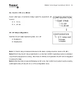
8.4. Conf. 0...10V or 4...20 mA:
Select what type of external analog signal the equipment will
receive:
❖
0…10 V
DC
❖
4…20 mA
8.5. UV lamp configuration
Switches the UV water treatment system on or off:
❖
Enabled (1)
❖
Disabled (0)
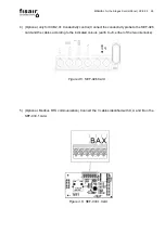
Note 1:
If the UV lamp is installed immersed in the basin, a bridge must be made in J18 (IN1)
Note 2:
Each time the UV lamp is switched on, an internal 12,000 hr operating counter is activated,
only when the equipment is running. After these 12,000 hours of operation, the A51 error is triggered
to replace the lamp.
Note 3:
After the lamp is replaced following an A51 error, the 12,000-hour counter must be reset by
switching the lamp off (0) and on (1) in this configuration menu.
Содержание CCE2.0
Страница 2: ...MANUAL for the Stages Control Panel CCE2 0 2 ...
Страница 11: ...MANUAL for the Stages Control Panel CCE2 0 11 5 Hardware description Figure 3 1 CCE2 0 front cover ...
Страница 13: ...MANUAL for the Stages Control Panel CCE2 0 13 Figure 3 3 CCE2 0 Open location SEF 028 1 and SEF 032 1 v2 cards ...
Страница 14: ...MANUAL for the Stages Control Panel CCE2 0 14 Figure 3 4 Inside cover CCE2 0 standard ...
Страница 53: ...MANUAL for the Stages Control Panel CCE2 0 53 13 Declaration of conformity 13 1 D C Machine ...
Страница 54: ...MANUAL for the Stages Control Panel CCE2 0 54 13 2 D C Partly completed machinery ...
Страница 55: ...MANUAL for the Stages Control Panel CCE2 0 55 14 Warranty ...
Страница 56: ...MANUAL for the Stages Control Panel CCE2 0 56 ...
Страница 57: ...IÓN F ...
Страница 58: ...IÓN ...
Страница 59: ...IÓN MAN P Ev1 Mv1 P P ...
Страница 60: ...F IÓN ...
Страница 61: ...IÓN ...
Страница 62: ...IÓN MAN P Ev1 Mv1 P P ...


