29
®
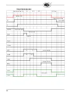
START-UP (NORMAL CYCLE)
Note:
For direct spark ignited oil burners, substitute the words Main-Oil Valve for Pilot Valve.
1.
Constant 120 VAC should be available to the Ll-L2 terminals only on the wiring base.
2.
The operating control circuits (Ll-3) will close, signaling the burner to start its firing sequence.
Terminal 13, fuel valve end switch must be closed.
3.
The burner/blower motor (terminal M) circuit is energized. The running interlock (limit) circuit
(3-P) will close (e.g. all limits, interlocks, etc. are proven).
4.
The firing rate motor (Modulator Motor) is driven toward the high purge open damper position
(10-X circuit made).
5.
When the firing rate motor reaches its open damper position, the Hi Purge switch closes (M-8)
and the prepurge interval of 30* seconds is initiated.
Assuming countdown method, the BLV512 will display:
If the M-8 circuit does not close, the program will hold in this position for ten minutes waiting
for it to close. If it does not, the control will lockout. If the M-8 circuit is closed at the start of a
cycle, the top line of a display will switch to PURGE 20 seconds.
If the M-8 circuit is not closed at the beginning of a cycle, the top line of a display will switch to
PURGE 10 seconds.
6.
When the prepurge is completed, the firing rate motor is driven toward the low purge damper
position (10-12 circuit made). The BLV512 will display:
7.
Following the minimum 30 second delay (to permit the firing rate motor to get to the low fire
position), the control will wait for the low fire switch (M-D) to close. When it closes, the trial
for ignition sequence will start. If after ten minutes, the M-D circuit is not closed, the control
will lockout unless selected to wait indefinitely.
8.
The trial for ignition period begins with Terminals 5, 6 and W being energized simultaneously.
This is known as PTFI (Pilot Trial for Ignition). The BLV512 will display:
Unless otherwise selected this period is ten seconds in duration. Terminal W will de-energize after 5
seconds. Refer to PTFI*MTFI TIMINGS to determine times selected or timings appropriate for the
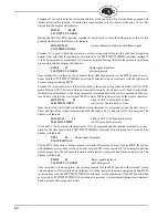
application. The test meter jacks on the YB110 (YB230) will provide an indication of the flame sig-
nal strength. The flame signal readout is also available on the alpha-numeric display.
PREPRG
00:25
HIGH FIRE PURGE
PURGE 00:19
HIGH FIRE PURGE
PURGE 00:10
HIGH FIRE PURGE
PURGE
00:24
LOW FIRE PURGE
PTFI 00:02
IGNITION TIMING
MINIMUM ACCEPTABLE
6mA
6-16
NORMAL
7.5 -20mA
20-80
TEST JACKS
DISPLAY


