


Firepower MST 140i
INSTALLATION, OPERATION AND SETUP
3-4
Manual 0-5338
5. Earthing of the Workpiece
Where the workpiece is not bonded to earth for
electrical safety, nor connected to earth because
of it’s size and position, e.g. ship’s hull or building
steelwork, a connection bonding the workpiece
to earth may reduce emissions in some, but not
all instances. Care should be taken to prevent the
earthing of the workpiece increasing the risk of injury
to users, or damage to other electrical equipment.
Where necessary, the connection of the workpiece
to earth should be made by direct connection to
the workpiece, but in some countries where direct
connection is not permitted, the bonding should be
achieved by suitable capacitance, selected according
to national regulations.
6. Screening and Shielding
Selective screening and shielding of other cables
and equipment in the surrounding area may alleviate
problems of interference. Screening the entire
welding installation may be considered for special
applications.
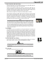
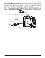
3.06 Firepower Flowmeter/ Regulator
Flowmeter/ Regulator (Figure 3-1) attached to the cylinder
valve reduces high cylinder pressures to suitable low working
pressures for welding, cutting, and other applications.
LOW PRESSURE
GAUGE (DELIVERY)
HIGH PRESSURE
GAUGE (SUPPLY)
INLET
CONNECTION
OUTLET
CONNECTION
PRESSURE
ADJUSTING
SCREW
A-12435
Figure 3-1: Firepower CS Flowmeter/ Regulator
!
WARNING
Use the flowmeter/ regulator for the gas and
pressure for which it is designed. NEVER alter a
flowmeter/ regulator for use with any other gas.
NOTE
Flowmeters/ Regulators supplied with 5/8" -18
standard inert gas connections. Flowmeters/
Regulators purchased with open 1/8”, 1/4”, 3/8”,
or 1/2” NPT ports must be assembled to their
intended system.
1. Note the maximum inlet pressure stamped on the
flowmeter/ regulator. DO NOT attach the flowmeter/
regulator to a system that has a higher pressure
than the maximum rated pressure stamped on the
flowmeter/ regulator.
2. The flowmeter/ regulator body will be stamped “IN”
or “HP” at the inlet port. Attach the inlet port to the
system supply pressure connection.
3. If gauges are to be attached to the flowmeter/
regulator and the flowmeter/ regulator is stamped
and listed by a third party (i.e. “UL” or “ETL”). The
following requirements must be met:
a) Inlet gauges over 1000 PSIG (6.87 mPa) shall
conform with the requirements of UL 404, “In-
dicating Pressure Gauges for Compressed Gas
Service.”
b) Low pressure gauges must be UL recognized for
the class of flowmeter/ regulator they are being
used on according to UL252A.
!
WARNING
DO NOT use a flowmeter/ regulator that delivers
pressure exceeding the pressure rating of the
downstream equipment unless pro visions are
made to prevent over-pressurization (i.e. system
relief valve). Make sure the pressure rating of the
down stream equipment is compatible with the
maximum delivery pressure of the flowmeter/
regulator.
4. Be sure that the flowmeter/ regulator has the correct
pressure rating and gas service for the cylinder used.
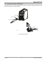
5. Carefully inspect the flowmeter/ regulator for
damaged threads, dirt, dust, grease, oil, or other
flammable substances. Remove dust and dirt with a
clean cloth. Be sure the inlet swivel filter is clean and
in place. Attach the flowmeter/ regulator (Figure 3-2)
to the cylinder valve. Tighten securely with a wrench.
Содержание MST 140i
Страница 6: ...This Page Intentionally Blank ...
Страница 76: ...Firepower MST 140i BASIC WELDING GUIDE 4 24 Manual 0 5338 This Page Intentionally Blank ...
Страница 82: ...Firepower MST 140i KEY SPARE PARTS 6 2 Manual 0 5338 6 02 Power Source Art A 12518 31 ...
Страница 86: ...Firepower MST 140i KEY SPARE PARTS 6 6 Manual 0 5338 This Page Intentionally Blank ...
Страница 87: ...Firepower MST 140i Manual 0 5338 1 APPENDIX APPENDIX This Page Intentionally Blank ...
Страница 88: ...Firepower MST 140i APPENDIX 2 Manual 0 5338 8 I Art A 12517 APPENDIX Firepower MST 140i CIRCUIT DIAGRAM ...
Страница 89: ...Firepower MST 140i Manual 0 5338 3 APPENDIX Art A 12517 ...


