
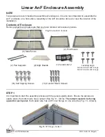

AnF Enclosures
REV. 8-29-18 Page 8
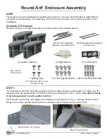
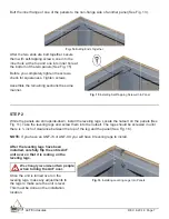
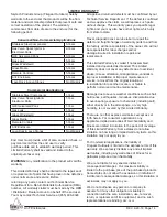
Fig. 17
Pan Support Placement
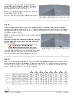
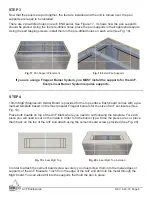
Fig. 18
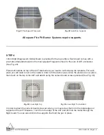
Install Pan Supports
If you are using a Firegear Burner System, you MUST install the supports for the AnF.
Every Linear Burner System requires supports.
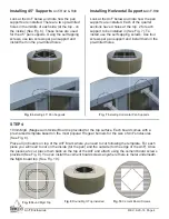
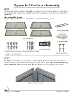
STEP 4
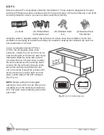
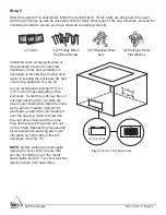
10mm MgO (Magnesium Oxide) Board is provided for the top surface. Each board comes with a pre-
marked template based on the most popular Firegear burners for the size of AnF enclosures (See
Fig. 19).
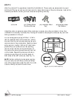
Place both boards on top of the AnF. Mark where you need to cut following the template. For each
piece you will need to cut on the inside in order to fi t the burner type. Once the pieces are cut, place
them back on the top of the AnF and attach using the cement board screws provided (See Fig. 20).
Fig. 19
Linear MgO Top
Fig. 20
Linear MgO Top Installed
In order to attach the cement board screw securely, you must screw them into the metal edges or
supports of the AnF. Measure 1 inch from the edge of the AnF and drill into the metal through the
MgO board. You can also drill into the supports that hold the pan in place.
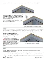
STEP 3
Now that the panels are put together, the feet are installed and the unit is turned over, the pan
supports are ready to be installed.
There are 2 pre-drilled holes on each END panel. See Figure 17 - it shows how the pan supports
should be placed. Using the four pre-drilled holes, place the pan supports in their appropriate spots.
Using the self tapping screws, install them in the pre-drilled holes on each side (See Fig. 18).


