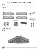
AnF Enclosures
REV. 8-29-18 Page 11
STEP 3
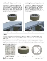
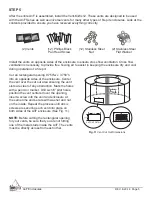
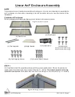
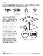
Now that the panels are put together, the feet are installed and the unit is turned over, the pan
supports are ready to be installed.
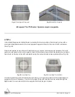
There are pre-drilled holes on the panels. See Figure 27 - it shows how the pan supports
should be placed. Using the two pre-drilled holes, place the pan supports in their
appropriate spots. Using the self tapping screws, install them in the pre-drilled holes on
each side (See Fig. 28).
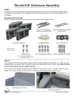
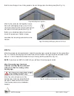
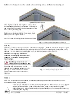
Butt the inner fl ange of one other panels to the non-fl ange side of another panel (See Fig. 24).
After the two ends are butt together, secure them
with self-tapping screws; one into the inner hole at
the top and one into inner hole at the bottom of the
two sections (See Fig. 25).
Before you completely tighten the screws, check
for squareness. Tighten screws.
Assemble the remaining panels the same manner.
Fig. 24
Butting Ends Together
Fig. 25
Installing Self-Tapping Screws Into Panel
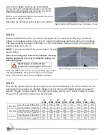
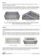
While the panels are still upside-down, install the leveling legs. Locate the nutsert on the panels (See
Fig. 11). Take the leveling legs and screw them into the nutsert. The legs should be screwed in until
there is 1 inch of clearance between the top of the leg and the panel (See Fig. 26).
Fig. 26
Installing Leveling Legs Into Panels
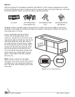
After the leveling legs have been
installed, carefully fl ip the entire AnF
unit over so that it is resting on the
leveling legs.
Once the AnF is turned over on the
leveling legs, make any adjustments to
the legs to make sure the unit is level.
This must be done in the installation
location.
STEP 2
We strongly recommend two
people when turning the AnF over.


